Relays
Electromechanical Amplifiers and Non-Linearity
Labs for 6.S917 are pretty easy-going. It is IAP and you're taking this for general interest. There are no checkoffs. There will tend to be some schematics, descriptions, instructions, and then it is up to you. Parts should be in the lab space, though cheapies/passives (like resistors, caps, etc...) may need to be harvested from the 5th floor stock room. I'm more than happy to help if I'm around and free or doing office hours! If you see another student working on stuff, bug them if you need help or if you want to offer help! The point of these labs is to appreciate electrical phenomena.
The Predicament
As hinted in lecture, the appearance of the vacuum tube in the first few years of the twentieth century yielded a device that could provide:
- Reliable amplification and
- Reliable non-linearity.
Amplification is important because signals inevitably lose strength as they are handed from one party to another (or one circuit to another). Nonlinearity was important since it provided the ability to do higher-order math with our circuits...this is exactly the same reason you need some sort of non-linearity in your neural nets in your ML classes for them to do anything useful beyond linear classification, in fact.
However, tubes weren't "invented" until ~1906 and it took another ten years for them to become widely available in production (~1920) and even then they still had their downsides. Prior to this, society still accomplished a lot (telegraphy, telephony, radio, primitive control theory), but it was just mostly done using electromechanical means (and some other early things...see next lab). To understand why vacuum tubes and semiconductors were such a critical development, we need to appreciate the limitations of electromagnetic/mechanical systems that they superceded...what did they do...what didn't they do...what was good/empowering...what was bad/limiting. We'll do that in this first (quick) lab. We'll look at how detection and amplification of signals could be done using just electromagnetic devices.
Inductors
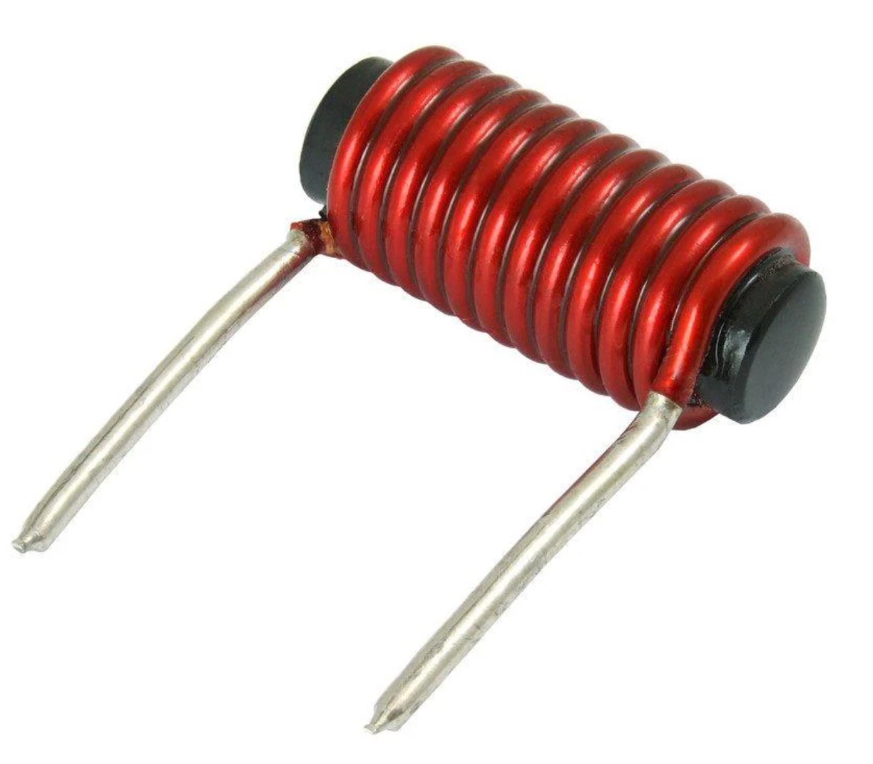
For quite a few decades, most electrical equipment was reliant on electromagnetic sensors and actuators. At the core of these devices were coils, which we usually call "inductors" in circuit land. Once we had figured out how to make wire, I'm assuming inductors came shortly thereafter when some nervous fidgety person was twisting wire around their finger and noticed interesting behaviors. An inductor might look like this:
Schematically a coil/inductor looks like this:

or this with more artistic loops:

As 8.02/Physics II should have taught you, inductor is nothing more than wire run in a certain number of loops. When current runs through any wire, you get a magnetic field around it. All a coil is doing is being a convenient and reliable means of stacking/packing that magnetic field from a lot of wire into a relatively tight space.
If you have a coil, the magnetic field B you can generate is roughly based on the equation:
where \mu_0 is the permeability of free space (universal constant related to c of 1.256\times 10^{-6} T\cdot A^{-1}), N is the number of coils, and l is the length of the coil, and I is the current through the coil.
From the electrical side, you can also get the famous inductor equation can be derived to be:
where A is the cross-sectional area of the coil. The inductor equation is less concerned with the magnetic field that is generated from a coil and more how it behaves from the perspective of the circuit.
Sometimes, the coil will have a chunk of material through its core. This is usually done because it can greatly increase the amount of field and inductance you can get per unit volume (the inductor in the first figure above is a cored inductor, for example). In that case, the field equation becomes:
and the inductor equation will be modified like:
In both cases, the \mu_r term is greater than unity (often much greater than unity) based on the core material:
A coil/inductor with a core will usually be drawn like this:

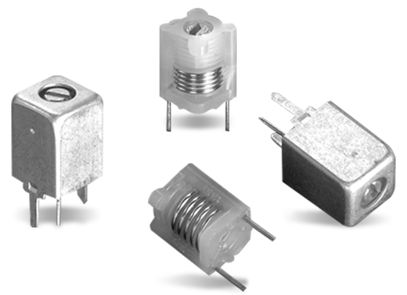
The fact that the inductance, L of a coil can be based off of this core material, also provides a means of conveniently adjusting the indutance by varying the fraction of the core that is air/free-space or the ferrous core material. If you've ever opened a radio up and seen the little metal boxes with weird flathead screw tops like shown below, these are slug tuners (essentially adjutable inductors that one would use to tune the values of L in a circuit...the complement of trimmer capacitors):
But we are digressing a little bit. This is thinking of coils as linear circuit elements (which can be useful), but is beside the point for right now...we will return to inductors and transformers in the future...instead let's get back to thinking of them as devices that allow us to induce a magnetic field based off of applied current.
If you have a coil and just by making electricty run through it you can make a strong and reliable magnetic field, you can set things nearby to be influenced by that magnetic field. We've all played with magnets. They can make things move.
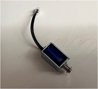
What could you move? Maybe a piece of metal that rings a bell. Or stamps a piece of metal, or unlocks/locks a door, or many other things. This is the foundation of a solenoid or even a motor or a audio speaker. All of these are coils inducing motion towards various ends. The possibilities are endless.
A Reed Switch
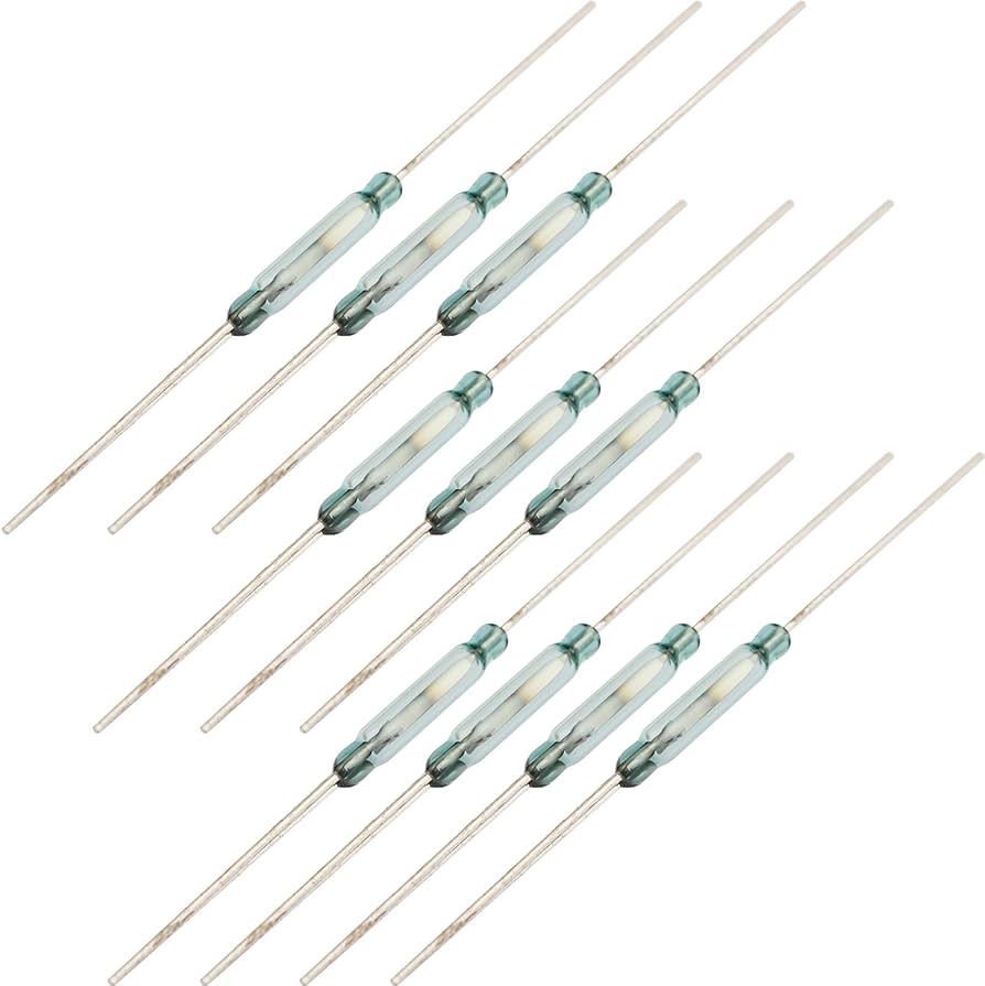
Another thing you could do with the magnetic field is open or close an electrical switch. Think about it...a switch is just metal...I mean it has to be in order to conduct. Metal can be ferrous. What if you set up your switch so that you could open or close it based on the magnetic field? Reed switches are switches designed just for this purpose:
The symbol for a reed switch usually looks something like this:

A reed switch is comprised of a pair of contacts that have just a little bit of overlap longitudinally and are separated by just a little bit of a gap transversally. The pieces of metal have a bit of flex in them. In their normal state, they do not touch, and therefore from one contact to the other there is no conduction. However if a small magnetic field is exposed along the axis of reed switch, the two flexible contacts straighten out and make contact. In the process, from one electrode to another, you can get conduction.
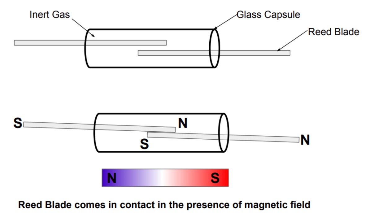
I have some reed switches in class if you want to look at them. Feel free to grab one and hook it up to the ohm/continuity setting on one of the multimeters. Normally you'll see them open, but if you put a magnet near it, it'll close (and the meter will read 0 Ohms/short). Very cool. Believe it or not, reed switches and magnets are still used to this day in some low-cost door/window sensors (though they are getting to supplanted by devices that rely on the Hall Effect more and more).
Relays
So we have a thing that will make potentially meaningful mechanical movement given a small magnetic field (reed switch). We can put that reed switch close to our coil like shown below:

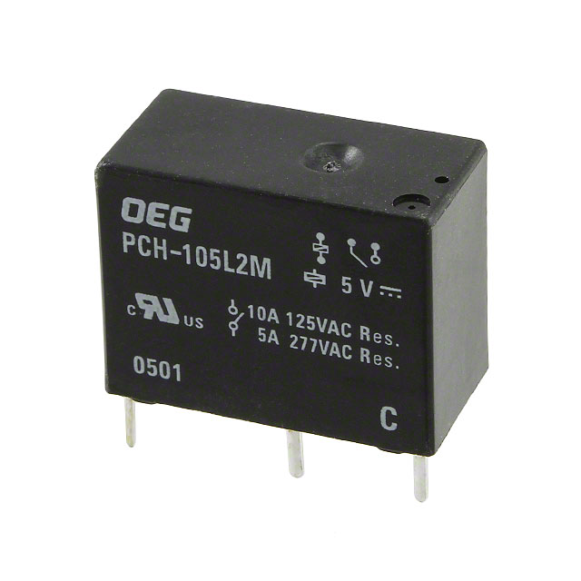
Now when current flows through the coil, you will cause the switch to close. The result of this is what's called a relay. You can have different types of relays, but among the simplest is a Single-Pole-Single-Throw (SPST) relay. That's what you have above and what it looks like in real life:
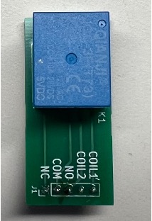
Another very common (and arguably more convenient) relay is a Single-Pole-Double-Throw (SPDT) relay. This is made by basically have two merged reed switches where one is in default contact with common terminal of the switch (Normally Closed of "NC") and one that is normally not in contact with the common terminal (Normally Opened or "NO").

We have a pile of these type of relays on conveniently labeled breakout PCBs for easy usage in a breadboard. You can use them to build the circuits at the end of the lab.j
There are, of course, more complicated relays, Double-Pole-Double-Throw (DPDT), Triple-Pole-Triple-Throw (TPTT), etc...we'll just use SPDT ones for now.
The Behavior
On paper, a relay seems useless...we have an electrical signal...we convert it to magnetic/mechanical and then go back into electrical. But this is misleading. That decoupling allows us to manipulate physics so that the incoming electrical signal can influence the outgoing electrical signal in ways that are advantageous.
Let's take the relays we have in lab...if we label the currents flowing through the relay like so:

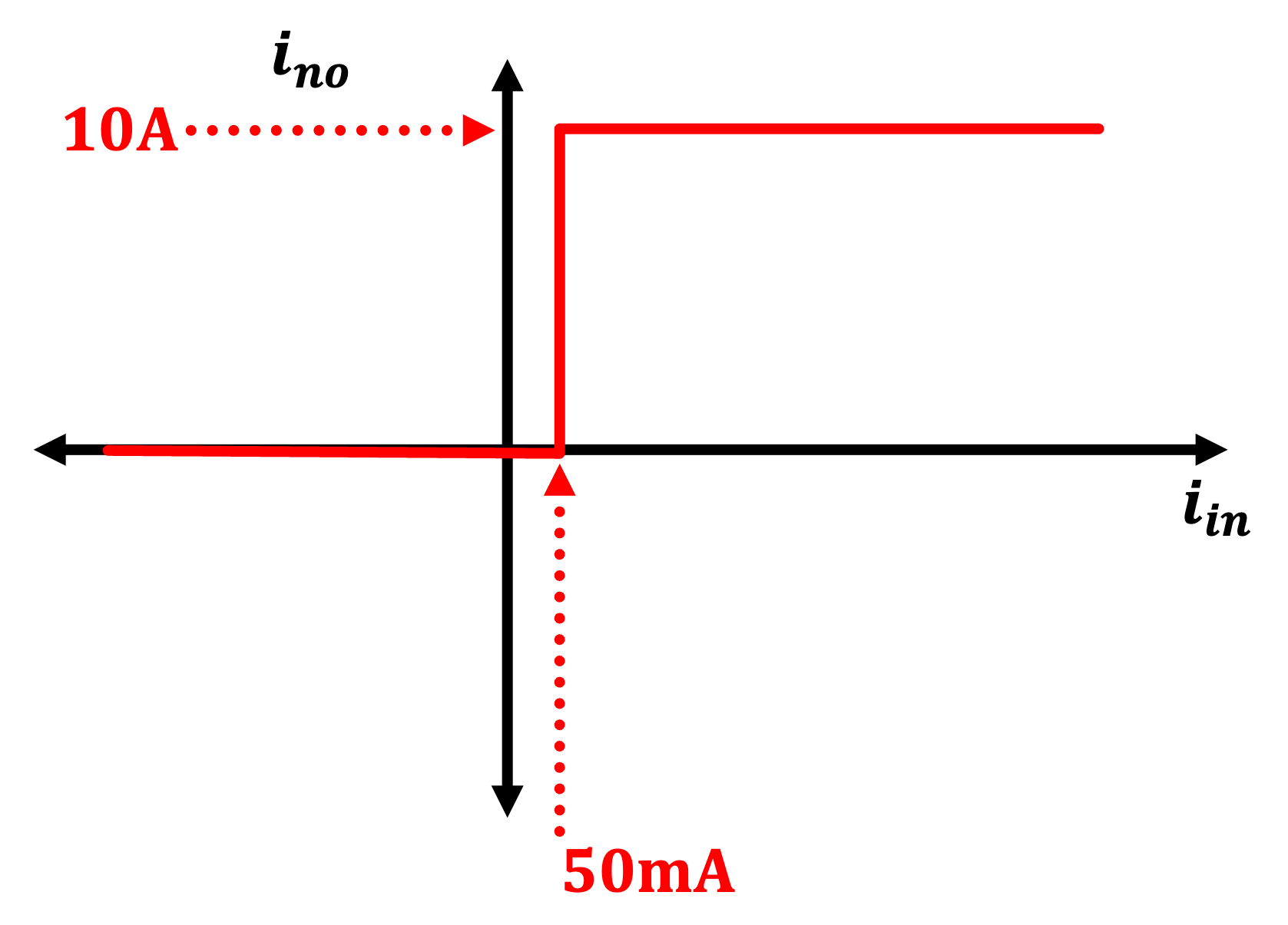
We can get two types of input-output behaviors from a relay like this. From the Normally Open terminal, you get this:
From the Normally Closed terminal you get this:
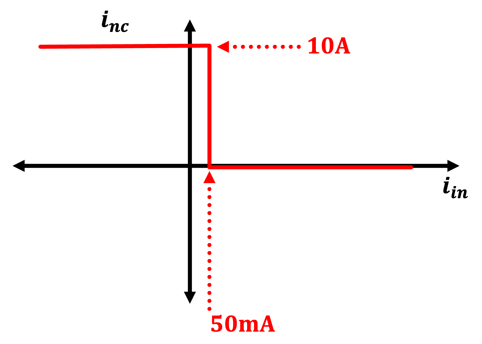
This is but one way to evaluate and plot the input-output relationship of a relay, but by looking at it as input/output current, the non-linearity and amplification aspect should become readily apparent. These relays have a pull-in current of about 50 mA, meaning when about 50 mA is flowing through the relay's coil, the magnetic field becomes strong enough to flip the switch of the relay. Below that (with some hysteresis mixed in), the switch flips back. This transition point is is sharp, electrically speaking...with basically infinite slope as far as we are concerned. This is highly non-linear.
Also because the switch can handle a lot of current, but the coil doesn't need too much, the relay is allowing a low-amplitude signal to create/control a high-amplitude signal. This is amplification. (with a 10A supply, this circuit could be said to have a current gain of 200 in fact).
These two attributes (lots of gain and lots of non-linearity), are foundational. Combined, they are enough to do quite a lot.
Three Circuits
Using these relays we could build a historically appropriate telegraph detector, but I think what might be more educational is to use their capabilities to create three important digital circuits:
- A NAND Gate
- A Set-Reset (SR) Latch
- An Oscillator
Circuit 1: NAND Gate
On a breadboard, using two relays, two button switches, an LED and a resistor, build the following circuit:

If we think of the buttons as digital inputs (not a hard stretch), with unpushed being "0" and pushed being "1", and use the LED as an output "D", we can get a rough pattern of its behavior. We can derive the following:
- A=0,B=0: C=1
- A=0,B=1: C=1
- A=1,B=0: C=1
- A=1,B=1: C=0
This pattern, is that of a NAND gate. NAND gates (and their siblings NOR gates) are each functionally complete. With them, you can build all other digital logic (both combinational and, if you add in feedback paths, sequential). You may think that would be an exhaustively massive undertaking that is only done theoretically, but that's actually wrong. The entire computer that controlled the Apollo moon lander in 1969 was built using on NOR gates for quality control reasons (of course by then logic was being done with transistors, but the fundamental idea remains the same. We'll get to that in a few weeks). So this is a pretty powerful circuit.
Circuit 2: Set-Reset Latch
The next circuit to build is a slight deviation on the previous. Instead of having the symmetry of the NAND gate, we'll change a few wires (shown in blue) and relable the two button inputs as "S" (for "Set") and "R" (for "Reset"):

The circuit works by starting as drawn in the "reset" state. If a user comes in and pushes the Reset button, nothing changes. If a user pushes Set, however, the button, allows current to flow through relay K_1's coil, causing its switch to flip towards the Normally Open connection. Since K_1's Common is connected to 5V, the resistor/LED combo connected to the Normally Open terminal will light up. Importantly, the Normally Closed connection of K_2 is also connecte here, and the Common of K_2 connects back to the top side of K_1's coil. This means the coil on K_1 is getting 5V supplied via two paths: The Set button and the path through K_1 and K_2. Now, even if the Set button is releaed, one of these paths is still existing and the circuit will stay "latched" in this state ("Set") until the Reset button is pushed, breaking this path.
The truth table for this circuit is the following:
- S=0,R=0: Q=\text{Latch}
- S=0,R=1: Q=0
- S=1,R=0: Q=1
- S=1,R=1: Q=0
The term "latch" in the truth table here refers to previous value of Q. In other words, this truth table is reliant on history...which means, the circuit is capable of remembering. This...is a big deal. With just two relays, we can have a circuit remember information. This is stateful. Put a few of these together and you can even make a D Latch...then a few more and you could have a D flip-flop, a clock-edge-triggered memory element that is the foundation of all modern sequential digital design.
Circuit 3: Oscillator
The previous circuit involved the left relay activating and then holding itself open until a second relay breaks the feedback path. Could we flip the tables on this and instead have a relay that is on turn itself off which then causes itself to turn back on which then causes it to turn itself off? In other words, the SR latch circuit had a relay in a stable feedback loop, could we instead set up a relay in an unstable feedback loop? Yes. The answer is Yes.
Build the circuit below. When you power it up, don't be alarmed by the ~1kHz noise.

That noise is coming from the inherent instability in the circuit. At power up, the relay is in its normally-closed position. Current flows throuh that branch, lighting up the LED an then also gets routed around through the relay's coil activating it. The relay then switches to its normally-opened position. This is fine, but current only flowed because the relay was in the NC position...so now there's now way for current to keep flowing and after the RL discharge, the relay will switch back from NO to NC, and the process will continue.
The frequency that this back-and-forth happens at is going to be hundreds of Hz....maybe 1kHz. You should use a scope to verify. You can slow this down by adding a capacitor in parallel with the relay coil like shown below. The capacitor's presence prevents the voltage across the coil (and subsequently the current through the coil) from building up until the capacitor has charged up. The bigger, you go with the cap value, the longer it takes the system to charge up. The capacitor also stores energy, so once the switch has happened, it will feed the coil for a while until the parasitic resistance in the LC circuit bleeds off enough for the relay to close again.

Reflections
A few big things to take away from these circuits. Relays on their own can provide us amplification and non-linearity. Those two attributes, together and in parts, can be used to create sufficient computation to build basically any modern electronic system. Literally you could build a neural net with them or an LLM....there's one big caveat...
Relays are slow. This arises from the fact that you're moving mass around to get behavior and that will always take some time, but also more fundamentally, relays rely on building up magnetic field to perform actions and that has a hard time scaling downward (in exponential ways like capacitance did in transistors in the latter half of the 20th century). Looking back on them from our 21st century perspective, the fact that they are stuckin the 100's of Hz response time really precluded them from doing any high-speed data processing. Their extremely digital nature doesn't actually even preclude them from being used for analog purposes (Class D amplifiers, which are how most modern systems generate audio are built around high speed digital switching and spectral filtering)...it really is just a matter of speed.
Just like neanderthals coexisted with early Homo sapiens for at least several thousand years, relays were widely used in many systems well into the 1950's, even though vacuum tubes were well-established by 1920. Part of this was because relays could be made to function for a very long time whereas vacuum tubes often had limited lifetimes of hundreds or thousands of hours (due to filament burnout and other things). Relays also could run on lower voltages and, amazingly, be more power efficient, which sounds comical given how we think of them today, but relative to the hungry hungry hippos that were vacuum tubes, they could be a good deal..
Interestingly enough, while not the focus of our class, relay-based logic like that shown above was how almost all computers were built up until about the end of the Second World War (~1945). In fact vacuum tubes were really only used heavily in computers for about ten to fifteen years (1945ish to 1955ish) since the sheer scale of computers made the high failure rates of tubes a really big problem. ENIAC, was the first "full" modern computer and it still had several thosand relays in some of its logic. Prior to that, however, Turing complete computers based solely off of relays were indeed a thing. The Zuse Z3 made by German scientists before and during World War 2, did all of its operations using 2600 relays, which when you think about it, isn't that crazy of a number. The Z3, however had a clock frequency of 5 Hz. That is not a typo. Not 5 GHz or 5MHz or 5kHz...5 Hz. This of course was because of the compounding of the resistor-inductor time constants of all the relays driving one another...I mean our relay oscillator ran at ~1kHz with nothing in between itself. Think about relays driving relays driving relays...the LR time constants would build up quickly.
After society collapses and you need to rebuild from scratch, relay-based logic will probably be your best bet to getting back to a functioning computer. Make a coil and a magnetic-field-based switch. Hook them up like shown above into a NOR topology, repeat several thousand times, and bingo bango bongo, you'll have a computer. The clock rate will be limited by greatly by the relay inductances and parasitic resistances, but at least it will work.
Further Readings
Claude Shannon's Masters Thesis from 1938, which establashes much of modern computing, uses relays as the bridge between boolean algebra and electrical manifestations of his ideas.
The Zuse Z3 computer was recreated in the early 2000's and documented here. Also this book goes into crazy detail on the designs and operation...all of this was done with relays, keep in mind.
Moving On
In the next lab we'll start to solve the problems of relays. The first issue we'll address is their low speed using an alternative technology that gives us non-linearity but can do so at very high frequencies (think radio). Then we'll use a different tech to give us non-linearity and amplification at high frequencies.