FM Radio
Non-Linearity
Note the video below is of a previous version of this circuit that used 9V and an audio amplifier chip. This year, we're using 3V and just a couple transistors to drive a pair of headphones. The relevant part of the circuit will still be the same and you should still hear audio, but it will be through headphones rather than through an "out-loud" speaker like shown here...I just didn't know how to record headphone audio.
Overview
In this lab you'll build a very basic FM crystal radio. While the detector you'll build is actually an AM detector, we'll use it in a manner known as "slope-detection" which allows us to coarsely convert frequency deviations into amplitude deviations via the rolloff of our selection filter and then demodulate it as if it was AM (see the appropriate slides from lecture 2 that cover this a little bit). Detection of AM requires non-linearity. I don't care what your so-called friends say....there is no way around it. In order to get some non-linearity, we'll use a diode. Historically this was obtained with Germanium or several other equivalents. We have some actual germanium ones in lab, but these are getting painfully hard to get. (I did get in some from former communist bloc countries (you can thank the collapse of the Soviet Union for this, which we'll discuss in greater depth when dealing with early transistors in a couple weeks).)...I also have a specific variant of metal-silicon Schottky diodes that have sufficient frequency response for our use, that also seem to work well enough (these are historically anachronistic, but are more available now).
I've gotten pretty good results with this radio around campus. I can get about six/seven different stations with ok-to-meh selectivity. In general this can be made to be a pretty sensitive receiver, however its selectivity (ability to discriminate different stations) is not amazing. There is no automatic gain control or anything like that here. Some stations are going to be freaking loud. Others very quiet. You will need to be adjusting your antenna position/orientation, capacitance, inductance, and volume as you tune. You (your body) and your physical location will be doing some tuning "twister". Some stations will only be obtainable with you holding the antenna in a certain way in a certain location1...this is not a radio where you set it and forget.
It may not work right away! It will be finicky! The values that matter for tuning are all in the picoFarad and sub-microHenry range. These are at the scale of parasitics! So have patience and enjoy! Imagine what it must have been like to do this in 1905.
I've tweaked and massaged this design so that it should be quite forgiving of some values. If you can't find a particular passive value, the "next one" in the drawer will likely work. Just don't go crazy and deviate by orders of magnitude. Feel free to remove parts to during experimentation. That's the best part to get a sense of why/what things do. I would suggest building the entire circuit, then verifying the audio stages work, and then with that known, going back and testing the crystal detector itself.
The Schematic
The circuit is comprised of two stages. The first is the actual crystal detector setup and what's relevant to the class for today. The latter stage with transistors is historically anachronistic for an early 20th century radio (bipolar juntion transistors not until mid-fifties), but we're using them so you can actually hear the audio without straining too much (and also because I don't have too many crystal earpieces to share and also sharing ear things is disgusting).
Complete Parts List
The full (I think) parts list is below. Most of the parts are in the boxes at the front of the lab. Some of the generic passives are in the parts drawers.
- Overall:
- Breadboard
- Jumper wire kit (optional or cut/strip your own wires from the spools)
- 2 AA batteries
- A 2AA battery holder
- Solder/Soldering iron
- Wire cutter/strippers
- Electrical tape
- Crystal Detector:
- Antenna/stick (hookup wire)
- Coil (from bare copper wire)
- Tuning Capacitor
- Plastic Base
- Plastic Knob, Washer, and Screw
- Germanium diode (or equivalent Schottky diode)
- 90K resistor
- 1 nF capacitor
- (Optional) Crystal Earpiece
- Audio Amplifier:
- 0.1 uF capacitor
- 910 KOhm resistor
- 5.1 KOhm resistor
- BC547 NPN transistor
- BC557 PNP transistor
- TRRS (tip ring ring sleeve) connector
- Pair of junk audio headphones
The Crystal Detector
This is the Crystal Detector portion of the circuit:

Here is the detector circuit. Since it is working at FM and we want to minimize loss we shouldn't build this part in a breadboard. Remember a crystal set is a completely inactive circuit...no amplification so the only signal we get out is what we recover from the ether. The parasitics in a breadboard would eat what little we do capture, so this needs to be built free floating which will need some soldering (there are irons around). If there were more parts in this circuit, we'd use a perf board, but honestly there's really only ~ four in the RF regime. Once we're to the right of the diode, you can go to the breadboard since we'll be in the audio range at that point. A general outline of the front-end parts and what they do and their values is below:
-
The Coil L_1 should be about 4 turns of heavy copper (bare) copper wire around a 1/2" form (I have some dowels for this purpose). I have a few spools of 18 AWG wire. Try to wind it so the total length is about an inch. Leave about an inch of bare copper at the beginning and end of each side of the inductor. Using a standard inductor formula like from this site we can see this works out to about 0.08 microHenries. If we need to tune the L down, you can stretch it out more...going to 1.5" gets it down to 0.05 microHenries, for example. The coil is actually acting like an "auto-transformer", but we'll talk about that in future classes.
-
The Antenna A_1 can be about several to 15 inches of regular 22 or 24 AWG hookup wire (use insulated wire off the spool). If you go long, Loosely wrap it around one of the long bamboo skewers in the parts area. Solder one side of the antenna to a tap about 1.5 turns in from the ground side of the inductor L_1.
-
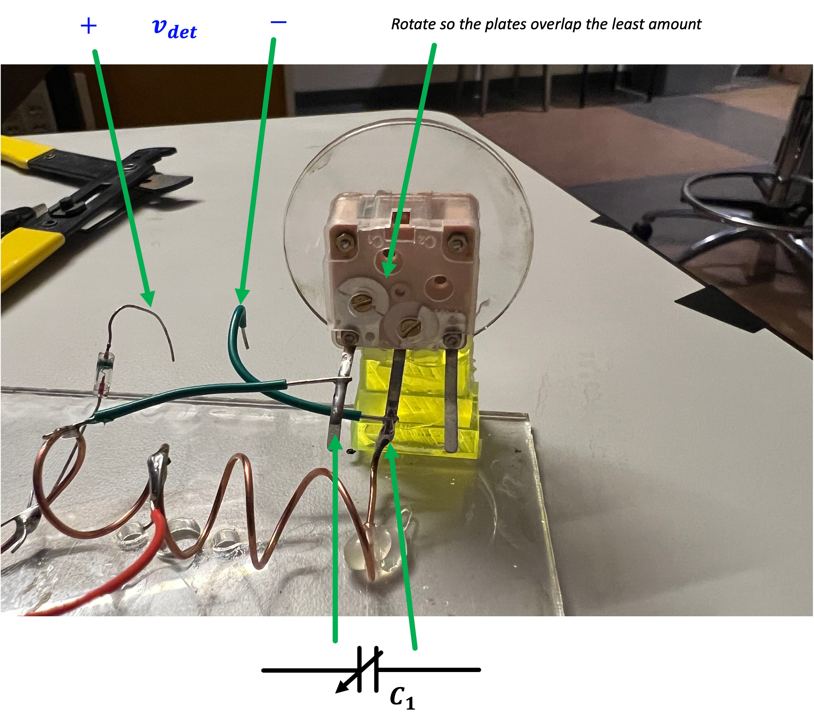
The Tuning Capacitor C_1 is one of the weird junk ones I got in bulk from Amazon here. Honestly these caps suck for what we need since the low range of the capacitance is actually a bit higher than we want, but they'll do. We will just likely need to lower L a bit more in order to get our L\cdot C product low enough so that our resonant frequency can get high enough to cover the entire FM band. The variable capacitor has two capacitors on that share the common middle lead. Looking from behind the tuning cap, use the left pair of leads for C_1. In addition, use a flathead to turn the inset trimmer cap about 180 degrees from its starting location. This will allow us to get the lowest possible value for C_1 at the rightward limit of turning (looking at it from the front). I've laser cut some "knobs" you can mount using an M2.5 screw and washer. I made a nice single-piece mount for the capacitor you can see in my working example in class. See my receiver at the front of class for how I mounted it.
- The Diode D_1 must be a germanium diode or equivalent. This is important since the "turn-on" voltage of a germanium junction is very low...approximately 0.2V to 0.3V. A silicon diode, for example has a turn-on of 0.7V. "Turn-On" is a misnomer...it really refers to where the diode has a nice non-linear "kink" in its I-V relationship. We want that kink to be as low as possible since it means we can encounter some legitimate non-linearity for as small as signals as possible. If the signals were coming in huge, you could totally use a silicon diode or even an LED (with their really large turn-on voltage), but that's not the situation we find ourselves in. The germanium diodes aren't plentiful. So don't mess them up. When soldering, try not to keep the iron on them too too long. As an alternative, I've found some Schottky diodes which are also a different type of metal-semiconductor diode using silicon. They are small and blue. Either should work.
- While we often think of diodes as "really" following the Schockley equation of some flavor like: i_D(t) = I_S \left(e^{\frac{v_D(t)q}{nkT}}-1\right), which would suggest that the behavior is arguably equally non-linear on its whole curve, in reality that's not quite how it works. There are other factors that come into play with diode curves and they usually won't work that way.
- As an aside, check out this cool site where some folks test out a whole bunch of different diodes and show their I-V curves. (scroll down for more filtered plots of sub-groups since that first plot is a bit overwhelming). You can see that they look exponential-ish but there's definitely an argument to be made that there's regions of linearness, then regions of "kinks" and then regions of other linear behavior. Hunt around through these curves and find Germanium, and particularly 1N34A. You can see that diode in particular has a nice kink in its I-V curve for relatively low values of v_D, which means, that we can hit that juicy, juicy non-linear region (with all of its higher-order Taylor Series expansion terms that give us multiplication and therefore demodulation as discussed in with much weaker signals than would be necessary with a something like a silicon diode.
Try to keep leads short where possible. Solder C_1 leads to the appropriate spots on the inductor using some wires with a little bit of breathing room so you can stretch the inductor out more if needed. Be careful soldering the coil. It is made of thicker copper so it'll take longer to heat up and will hold heat longer than you might expect.
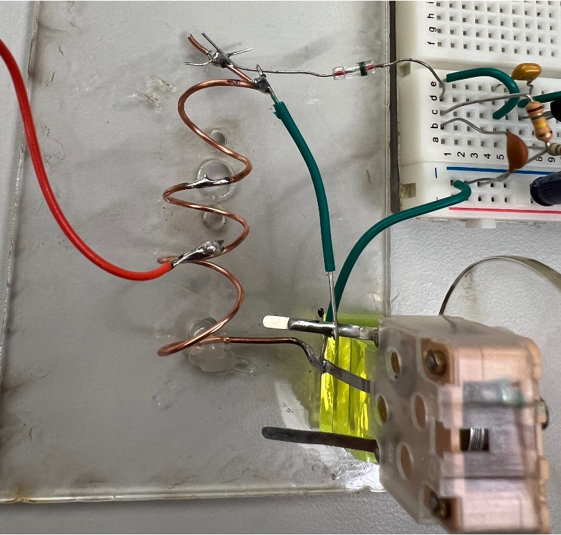
After the diode, you are in the land of low-pass (which for us is audio frequencies). Breadboards won't eat audio like they do RF, so the next two stages can be done on a breadboard (see how I set mine up). This is a bit more forgiving than all the soldering/floating wires. This includes the last two components of the schematic in Figure 1, which could be counted as either the output of our crystal detector or the input of our audio amp (nex section) tbh.
- Resistor R_1 and Capacitor C_2 form a low pass filter which essentially filters out all the high frequency components of our nonlinear demodulation from D_1 leaving just the low frequency goodness that we care about (the actual information). There's some flexibility in these values. I just used ones sitting on my bench. You want to target their time constant \tau to be about 0.1 ms (currently 0.09 ms with these values)....this gives us a cutoff frequency of around 10,000 rad/s or ~2kHz ish. This will allow any audio signals through but block any higher frequency crap. While their product is important, achieving it with too high a resistor/too low a capacitor or vice-versa can result in weird loading so try to stay in this neighborhood of values for both of them.
Once this is built, you should have a crystal detector. You may be getting signals right now. If you hook the output up to an oscilloscope, and adjust the tuning cap and antenna you might even be able to see something (tiny). Likely it will be underwhelming and/or hard to see (in the mV range).
Power?
Hey, Joe, you forgot the power. There's no way this circuit will work without being connected to a power supply. Well, my sweet summer child, the radio waves are the power in this portion of the circuit. In fact, with the right audio transducer, there's enough power here to even generate a slight audible signal!
The Audio Amplifier

You can either just build the circuit, or if you're curious how this thing works, I put some notes on it below:
Capacitor C_3 is an AC coupling capacitor, allowing the audio through but blocking any DC bias which would mess up the individual stages and their operations. 0.1 uF is a good value to use here. I found a bunch lying around. You could got a bit higher probably lower and little change would result.
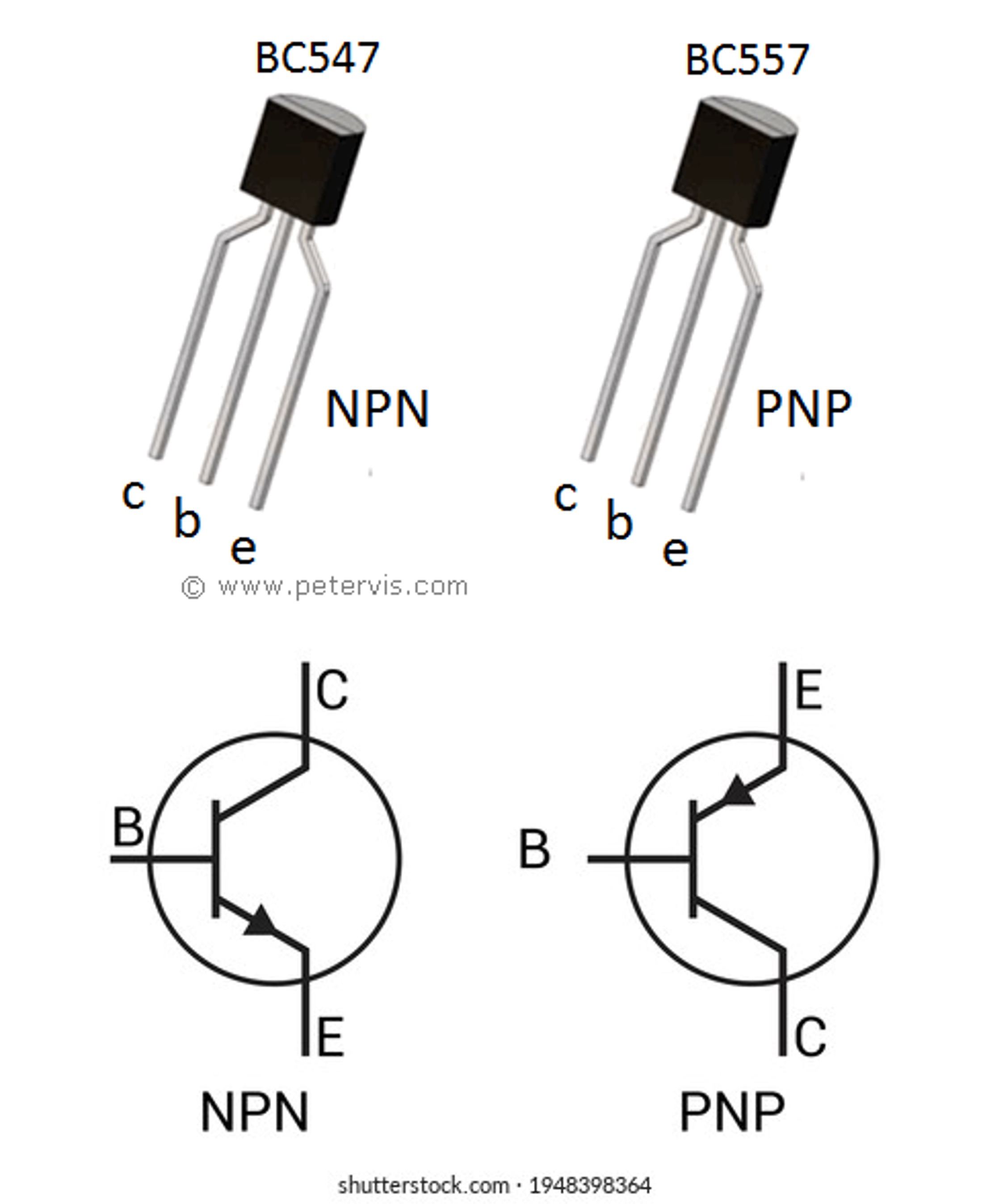
Transistor Q_1 gives the first stage of gain and transistor Q_2 gives a second stage of gain. Remember arrow leg is the emitter, middle leg is base, not-arrow-leg is collector2. Looking at a BC547 transistor from the front, leg order going left to right is Collectorr Base Emitter (note this is opposite of transistors like 2N2222 and 2N3904!!!). Same with the BC557 PNP transistor.
Resistor R_2 ties the base of Q_1 to 3V. As we'll see in a few weeks, if we assume the transistor is "on", there will be about a 0.7V drop from the base to the emitter of Q_1. This means at rest, there will be about 2.3V/910k\Omega \approx 2.5\mu A. flowing through R_2 and into the base of Q_1. Assuming Q_1 is in its active region, it will amplify this base current by about a factor of \beta\approx 100 (to about 0.25mA) and set this to be the current into/through its Collector i_{c1}. KCL tells us that current is supplied via two paths: resistor R_3, and from the base of Q_2. The voltage at the collector of Q_1 will get pinned to about 2.3V because the emitter-base drop of Q_2 will settle at about 0.7V if we assume Q_2 is also pulled into forward active mode. This means of the \approx 0.25mA flowing into Q_1's base, about 0.7V/5100\Omega\approx 0.130mA will be coming from R_3 and the remainder will be flowing from Q_2's base. Honestly, the value of R_3 isn't super important and strictly speaking it doesn't really need to exist, though for reasons of stability its placement isn't a bad idea....just don't make it too low else it'll keep Q_2's base-emitter voltage pinned to close to 0 and some of our assumptions will not be correct. The remainder of the bias current will flow from Q_2's base. It too will get scaled by a factor of \beta\approx 100 to yield a collector current out of Q_2 of approximately 100\times 0.125mA or about 12.5 mA into the speaker. Now in reality, the current amplification factors of Q_1 and Q_2 will not both be 100...they'll likely be significantly less, but they'll be something (and do roughly get multiplied together). The two transistors are being used in a circuit topology that is a approximatelySziklai pair, a circuit kind of related to a Darlington pair.
Now, when an demodulated audio signal comes in from the detector portion of the circuit, it will be in the form of a time-varying current. That current will be able to flow through C_2 and add/subtract to/from that initial base bias current into Q_1. The deviations in amount will be scaled by the same amount as the overall bias current, so we'd expect to see the current into speaker S_1 going up/down in response to audio signals. Time-varying current through a speaker will make it flex...and make sound.
Speaker
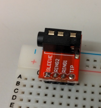
For a speaker we're going to use really, really junky airline headphones. They are stereo, with the left and right bud each being made of a 32 Ohm speaker. We're going to string them in series to get a 64 Ohm speaker. In order to do this, grab a TRRS breadboard adapter shown below. Set things up so that the Tip pin is your + end of the "speaker" and the Ring1 is the - end of your "speaker"
Note this circuit is running a DC current through the speaker headphones. This is never a good idea, since it can burn out the speaker, but it needs to be done here since we're dealing with such a low voltage/low signal, and also we're using real junk headphones so I don't care if they ultimately break. Note when you use this system, the earbuds may get a little warm when they're in your ear...in particular when there is no audio going through. Don't be weirded out by that.
Putting It All Together and Testing
I have a functioning version of the system at the front of class. Feel free to look/investigate it.
For testing and tuning, you need to realize a few things:
-
First, make sure you audio amplification pipeline is working. It would suck if it isn't. Touch the input to it with your finger. You should get some nice buzzing out of the speaker. If not, check your wiring. Make sure this is working first since we're going to rely on it (and our ears) to find stations.
-
When tuning, we are at FM so up in the 100 MHz range. The wavelengths here are a few (three-ish) meters which means that as you move around the room and rotate your antenna you will quickly encounter peaks and troughs of signal strength. This is cool, but can also be tricky. Lucky for us we are getting bathed in pretty strong FM signals on campus from some nearby commercial stations.
-
Have patience. You ever here that saying, "Don't get angry when you're stuck in traffic because you're part of the problem"...? Same thing here. You and your flesh with all its ionic juices are part of the tuning. When you are near your coil and capacitor, your body is adding/modifying those values. Embrace it. There's no shame to say, "well I get this station if I touch the coil with my finger and hold my arm this way." It takes some playing but hunt for stations.
-
These variable capacitors are kinda junky. They have some backlash in them so sometimes tuning into 17 pF from the left will work better than tuning into 17 pF from the right. As you learn more about your receiver you'll start to get a better sense of what works and what doesn't.
Is it Working?
If it is working, feel free to take a video to commemorate. You can hang onto the amplifier or put it on top of a bench with your name and a "DONT'T TOUCH" note if you want.
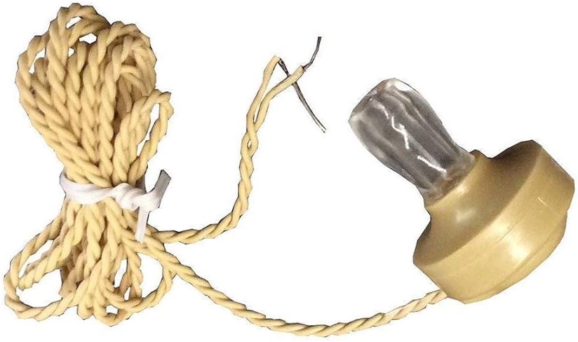
Crystal Earpiece
Your circuit is currently historically anachronistic because of the transistors. If you'd like to be really historically accurate, I have a few crystal earpieces in lab. They look like the following image and provide a high-impedance load for your crystal detector. This is desirable because they won't pull down detector output like a regular speaker or set of headphones would (crystal detectors are more capacitive in nature than resistive/inductive). With the crystal earphone you can actually run your circuit without any power at all, it'll just generate (very faint) audio off of the energy recovered from the radio wave. Sick.