Tube Ampliifers
An Audio Amplifier
The System
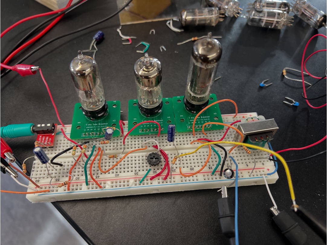
The amp in real-life is shownn below. I'll leave my working version in lab for you to check out in case you have any questions/issues.
The schematic for the circuit is below

The Tubes
We're using three tubes in this amp. Two 6J6 dual triodes and one 6AQ5 beam power tetrode.
The 6J6 Triode (Tubes Q1 and Q2)
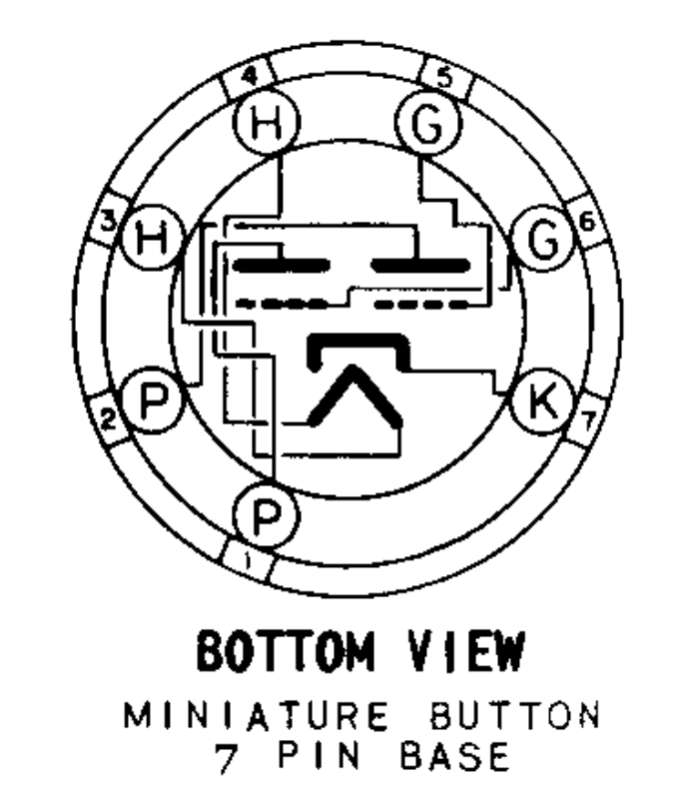
We'll be using two 6J6 dual triodes for the first three stages. This is a 7 pin "miniature" tube, made of all glass. The data sheet is here. It is comprised of two triodes that share a common cathode. It was originally intended for RF work during the Second World War (1944 release date I believe), but found a second "life" in some early vacuum tube computers which caused them to manufacture large volumes. Since it isn't particularly good for audio (one of the only remaining markets for tubes with any sort of volume and demand), you can buy these things for next to nothing, and I can find them in bulk on the internet. The tube's pinout is shown below. Note:
- Pins 3 and 4 are the filament. This must be at 6.3V. the tube's heater consumes 0.45A @6.3V so about 2.8 W (it gets toasty).
- Pins 1 and 6 control the plate and grid, respectively of one triode.
- Pins 2 and 5 control the plate and grid, respectively of the other triode.
- Pin 7 is the cathode, common to both triodes.
In case it isn't clear, the two triodes can be controlled separately, however the fact that they share a cathode does limit how "separate" they can be (certain circuits and topologies aren't possible).
The data sheet for this tube, like most tubes, gives juicy details and shows its behavior over several hundred volts.
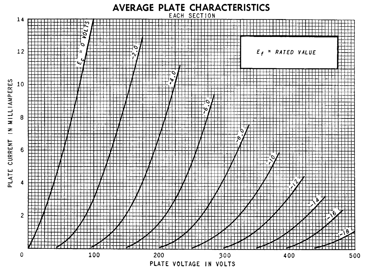
We'll be using them in the very tiny lower left corner of their operation range. To make the tubes easier to work with in the breadboard, I fabbed and soldered up some nifty little tube breakout boards with the pins labeled and everything. There's a box of them up front.
Note that the first two stages of the amplifier use one single tube so each half is drawn separately in the schematic, but only one shows the filament connection, since it is "taken care of" by already being connected for the first triode (tubes are marked Q1(A) and Q1(B) to stress this.
The third stage of the amp actually runs both halves of the tube in parallel to increase the gain we get out of it (so the tube acts as one single slightly-better triode).
The 6AQ5 Beam Power Tube (Q3)
The last stage of the amplifier, the "power amplifier" is built around a 6AQ5. The 6AQ5 is actually a legit good tube for audio (unlike the 6J6), having been used as the output stage of television sets and budget stereos for several decades, but its maximum voltage is quite low (like 200V) so it is often forgotten by audiophiles; since we're running our amp at 32V, though it doesn't matter. Its datasheet is here.
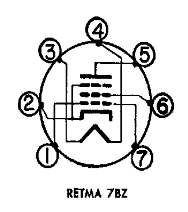
You may notice this tube has a lot more connections and things going on than the 6J6 (and it is a single-element tube unlike the 6J6 which was a dual triode). The 6AQ5 is a beam-power tube. It has three types of grids instead of the usual one of a triode. You could therefore call it a "pentode" and it will indeed often be called that. Its top most grid isn't really a grid though and is more a set of shaping electrodes that are always tied to the cathode that focus the electron stream into a very tight beam enabling the power output of the tube to be higher than it normally would be. Because of this sometimes folks will say this is a beam-power "tetrode" since there's really only two grids that can be controlled.
- Pins 3 and 4 are the filament. This must be at 6.3V. the tube's heater consumes 0.45A @6.3V so about 2.8 W (it gets toasty).
- Pins 1 and 7, redundantly, both connect to the control grid of the tube.
- Pin 2 is the cathode/beam-control electrodes.
- Pin 5 is the plate of the tube.
- Pin 6 is the "screen" grid of the tube. This tube electrically shields the cathode from the control grid, suppressing Miller capacitance as well as largely decoupling the influence of plate voltage on plate current above a certain threshold (this is what ultimately gives us the classic I-V curves of a tetrode/pentode with their flat regions...more on this in Week 3!)
The Circuit
Power Supplies

This circuit will have two different power supplies. Make sure you connect their grounds together so they are common.
- The B+ power supply willl be 32 V. The current draw on this supply will be minimal (maybe 100 mA max and likely far less).
- The A supply will drive the filaments. It should be set to be 6.3V. We need to heat all three tubes up and since each one pulls 0.45A max at 6.3V we should expect the power supply to have to drive around 1.35A. On the power supply, make sure to set a current limit of about 1.4A for the A supply. This will limit in-rush current when the tubes are warming up!
When testing/debugging, make sure to bring up the A supply first and let it stabilize before turning on the B+ supply!
Stage 0: Inputs
The circuit uses a TRRS connector for its audio input. I have some phone adapters and some 3.5mm cables for connecting your systemt to a audio source. Resistors R_1 and R_2 equally combined the left/right audio channels and then the signal is run through C_1 which acts as a DC-block capacitor, letting only the AC (the music part) of the signal through. This is important so we do not interfere with the biasing of the grid in the first stage.

Stage 1: Voltage Amplification
The first half of tube Q1 is used as a common-cathode amplifier. The job of this stage is to produce some voltage amplification. Notice the cathode of the tube is tied to ground. This means we need the grid to be below ground in potential. Since we don't have a negative rail power supply, we're going to instead use grid-leak biasing to achieve this (see lecture 4 notes). That is the job of resistor R_4. It provides a stabilizing path for the electrons that build up on the control grid to a known reference potential. A value of 3.3 MegaOhm was chosen since that ends up biasing the grid a few hundred millivolts below ground, which is what we want.
Resistor R_3 is a "grid stopper" resistor. It helps suppress ringing and noise in the circuit. It isn't strictly needed, but if you do remove it, you'll notice your audio output might be a little more "ringy" or "tinny."
Resistor R_5 is our gain control resistor. This value roughly sets the voltage gain of the stage. The output impedance of a triode is quite high however (the I-V curves are not horizontal!) so we can't arbitrarily set this value for more or less gain. This was determined through experimentation.
The output of this circuit is at the plate of the triode (right below R_5).

Stage 2: More Voltage Amplification
The second half of triode Q_1 is acting as a second voltage amplifier, nearly identical to the first. The tubes are quite limited at these low voltages, so doing two medium-gain stages of amplification, rather than one large stage of amplification because it makes things easier.
C_2 is a DC-blocking cap, letting only the audio through from the previous stage. This signal travels through another grid-stopper resistor (R_6) and into the control grid. Just like in stage 1, this stage gets its grid bias from a grid leak resistor (R_7). This sets the stable/operating point of the grid to be less than 0V which then lets the tube operate effectively (since its potential will below the cathode. Resistor R_8 again sets the amount of gain in the circuit and the output of this stage is taken at pin 2, the plate of this triode.

Stage 3: Cathode-Follower Buffer
We'd now like to add some volume control to the system. We could do this with a potentiometer, but since we're operating at very low voltages on the tubes, the input impedance to each tube is relatively low, and the output impedance of each stage is relatively high meaning it is very hard to hand signals between each stage without significant signal loss. If we were to just use a potentiometer as a variable-voltage divider load at the output of the previous voltage amplifier stage and then use the tap value to drive the next stage we'd have a hard time moving the signal. This is because the output of Stage 2 wants a thing that is inherently in conflict with what the input of Stage 4 (our power amplifier) wants. Specifically:
- Stage 2 wants to drive a large load. So we'd want to pick a large value of the potentiometer (like 1 M).
- Stage 4, the power amplifier, wants to be driven by a low value impedance so it gets as much signal amplitude as possible. It therefore wants a very low potentiometer value...like 10 K).
A single potentiometer can't do this so instead we'll put a circuit in between that acts as a conflict mediator. Specifically this will be a Cathode Follower. We'll talk about details of cathod followers in lectures 4 and 5, but what it basically provides is:
- A high input impedance
- A (relatively) low output impedance
- Just about unity-gain voltage amplification, but in the process provides some power amplification.
We'll use both halves of Q_2 in parallel to act as a super triode to provide even a bit more oomph. Note that the plate of this tube is tied directly to B+ rather than througha resistor. The voltage that appears at the output of the circuit, taken at the cathode (pin 7) will roughly follow the signal put in at pins 5,6 (the grid). This is where the nomenclature "cathode follower" comes from...the cathode follows the grid....sometimes this circuit will also be called a common-anode or common/plate amplifier.
What we get though is a potentiomter that can be used as a volume control and which provides a relatively low-impedance source impedance to our final stage, the power amplifier. Again, C_3 is acting as a DC-block.

Stage 4: The Power Amplifier
The final stage of our amplifier is concerned with putting as much power into our speaker as possible. It is using a tube with a higher current output (a beam power tube). It is still essentially a common-cathode amplifier (like stages 1 and 2). k A grid-leak bias resistor R_{10} that is relatively small ties the grid voltage to very close to 0. In order to get the grid to be negative, however, this time we're going to use cathode biasing. We put a resistor R_{11} from cathode to ground. This means that at rest, when current is flowing, voltage builds up across it, making the rest voltage of the cathode several volts. Since the control grid stays about at 0V, this means we get a negative grid bias through this mechanism. The presence of a cathode resistor does shunt out voltage gain though (in fact this is how the cathode-follower in the previous stage works) so we put a bypass capacitor C_4 which "removes" R_{11} at audio frequencies...as a result we get the best of both worlds. Positive cathode voltage at DC and little cathode voltage at AC/audio.
Since this is a common cathode amplifier, the "load" of the circuit will be at the tube's plate/anode (pin 5). We could hook that directly into the speaker, but since the impedance of the speaker is very small (like 8 Ohms), the output impedance of our beam power tube is not super low (like 1000 Ohm or so), and we are concerned with power transfer, the tube is going to have a really hard time handing much power off to the speaker. Instead, we're going to use a audio-transformer which is used to adjust the impedance of the speaker. This adjusts the voltage/current ratio requested by the speaker to a form that is much more compatible/complementary to the tube's output. The speaker is made to "look" like 1000 Ohms with this device so it is as if a 1000 Ohm resistor is placed there for the load. Significantly more power gets delivered to the speaker than would have otherwise been possible.

Build and Analyze
Build the circuit and test it out. With the volume knob at "full" blast, you probably don't need too much volume from your phone/laptop whatever. I have some raw speakers in lab as well as some speakers in actual housings. The ones in housings will sound better because (believe it or not), a good speaker housing is a form of mechanical impedance matching ensuring efficient energy handoff from the speaker into the audio domain.
Anyways, all the parts shuld be in lab. A working version is at the bench where I've been sitting. Ask questions and hack away.
The plate voltage is limited to 32V so while "safe" make sure to still turn off the circuit fully when debugging it. Also when powering up, remember to do the filament voltages (A supply) first and then do the B+ supply after the current has stabilized and the tube are warm and glowing.