Making Some Electrons Flow
The Vacuum Fluoresent Display
Before OLEDs and before LCDs and before LEDs the options for small displays on electronics were quite limited. There were Nixie Tubes, everybody's favorite vintage display that used an anode in conjunction with cold cathodes shaped as differents symbols inside a tube filled with what was usually Neon gas. There were also many other technologies, which we could go into if people are interested. A widely-used display tech from the early 1960s up until the 2000's was the vacuum fluorsecent display or "VFD" for short. VFDs came in a vast array of shapes and sizes, but they were at their core all vacuum tubes using thermionic emissions. A cathode would be heated and start to emit electrons. Nearby anodes (aka "plates") would be set to positive voltages and the electrons would flow towards them. Upon impact, the electrons would collide with various phosphors that the plate would be coated in, causing light to be given off. Lots of different colors were possible, though the cool Zinc-Oxide greenish-blue was probably the most common.
VFDs can run off of relatively low voltage (as far as vacuum tubes go), so I thought they'd be a nice fun thing to poke at before we hit the real tubes in Lab 04.
A Tale of Two or More Power Supplies
Vacuum tubes used several different power supplies. Usually it would be two, though sometimes it'd be three. They were:
- The A Supply, which was intended for powering filaments. This was usually a lower voltage (we'll use 2.0V in this lab and 6.3V in the next lab, but this could vary). In general the A supply was usually pretty high current (since the filaments were quite hungry).
- The B Supply...sometimes you'll see this as the "B+" supply or the "HT" (For High Tension) supply. This would often be 100's of volts and would be the power supply of the actual part of the circuit doing the amplification.
- The C Supply...not super common, especially in later circuits, but sometimes a C supply would exist for biasing tubes in particular ways. We won't have any C supplies in our class.
Find the power supply on your bench station. You're going to need to use both channels, one to make the filament (A) voltage, and one to make the plate (B) voltage. Do not mix them up; you'll destroy the tube.
The Tube (IV-25)
The tube we'll be using is the IV-25. It is a Soviet tube. The "datasheet" is shown below. T
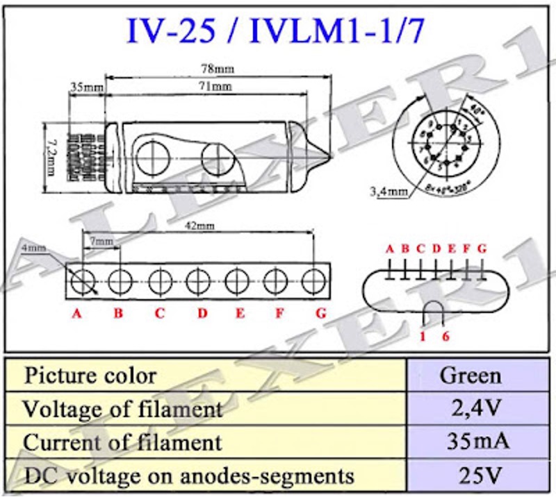
he IV-25 was a seven-dot column display. You'd heat up the filament and then apply ~20/25V to any/all of the plate/anodes you cared about to make them glow. It was meant to be used on its own or in large arrays to convey arbitrary graphical information. You could, for example, express a binary number, or perhaps a bar graph...the possibilities are endless.
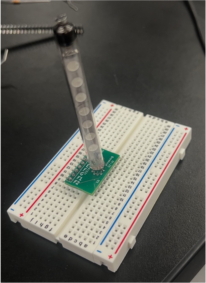

The device uses <2.5V for its A supply (we'll use 2.0V) and it uses 20 to 25V for its B supply. This is reasonably normal for a VFD (but again quite low for actual vacuum tubes like you'd find in an audio amplifier). I made some simple little breakout boards for these displays to save you from the frustration of wiring these things up. They're shown in th
Powering It Up
To get started, connect one of your power supplies (MAKE SURE IT IS OFF) to the filament pins (F1 and F2). This is going to be your A supply. Once done, set that power supply to 2.0V and turn it on. Observe the current being drawn...you should see anywhere from 0.02 to 0.03 A on the powersupplies. That should be in line with the datasheet. Note on VFDs, the filament is designed using materials that enable the electrons to be emitted without glowing...this is advantageous since the filament is right in front and if it were glowing orange, it would distract. As it is, it is effectively invisible in normal operation (though you can see it if you look close enough).
Next, take your second power supply. With it still turned off, connect its ground connection to the filament pin you set to be the ground connection from your A supply. Then take the + connection and attach it to one of the (you choose) anodes. Set the power supply to 0V and then turn it on. Gradually bring the B power supply up to 25V and observe when you start to see that sweet, sweet blue-green phosphor glow.
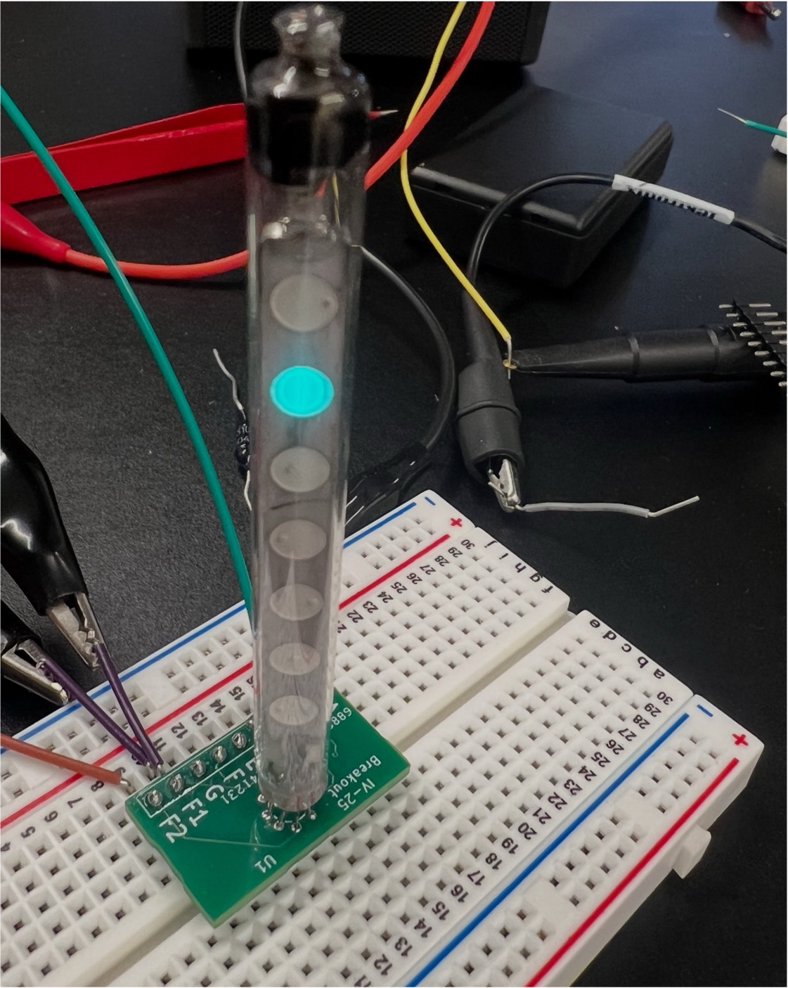
Feel free to connect more than one anode up to the B+ voltage. Feel free to turn on/off both supplies (don't increase filament voltage above 2V though). See how quickly the illumination comes on/off with plate/anode variations vs. filament on/off.
Other VFDs
The IV-25 tube that we're experimenting is actually somewhat of an odd VFD in that it has no control grid. Normally, a VFD will have an actual control grid between the filament and the plates. This grid is used to activate/suppress the stream of electrons and therefore turn on/off the tube in bulk. The thought process behind this is it would allow you to control many tubes in parallel using a much smaller set of pins. As shown in the diagram below, The "A" plates of multiple tubes would be tied together. By quickly cycling through the

The reason the filament on each tube wasn't turned on/off for the cycling was because the heat-up/cool-down thermal time constant was too slow.
Because you would have a filament/cathode, a grid, and a plate, the VFD in such a configuration was comprised of a triode, and believe it not you could actually get some amplification out of a VFD as a result. It was never intended this way, but hobbyists have indeed done this with surplus tubes for fun, and there is even a company that tried (is trying?) to make a chip using this technology for HiFi audio. Hmmm. Interesting.
Anyways, if anybody is interested in making a project with a more complicated VFD, let me know...I might have a few extras laying around. I had bought some nine-segment numerical ones, but they are proving a real pain to get the tubes out of. These tubes aren't necessarily expensive and they last really long times, just they are often a pain to wire up.
In the next lab, we'll build a legit tube audio amplifier!