Lab 3
Oscillations, Bistability, Pentodes
Tubes Driving Tubes Driving Tubes...
The circuits on this page are essentially snakes eating their own tails. One stage drives the next stage which then drives the first stage...and so on. Unlike with the snakes though, there's no self-destructive symbolism in play. These are circuits that achieve very useful functions and really touch on a whole lot of concepts, feedback, digital electronics, stability, time-constants, love, pain, beauty, etc...the list goes on.
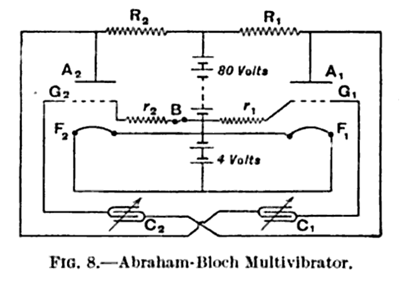
The circuit at the core of today is known as the multivibrator. They were first developeda around 1919 and were made possible because of the amplifying and inverting nature of your basic triode circuit like shown below. You'll recall from our class that in this standard configuration for a triode, you can get amplification, but the amplification will have a negative sign...so input voltage goes up a little, output voltage goes down a lot, input voltage goes down a little, output voltage goes up a lot. You get gain in terms of signal, it is just flipped.
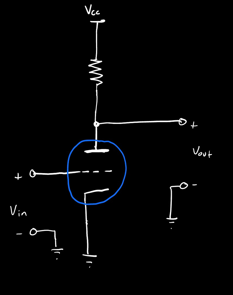
Digital circuits were still a ways off, but the triode circuit above, could be thought of as a primitive form of inverter. If we just classify our voltages as either "high" or "low" you can abstract a circuit like that with the following symbol:
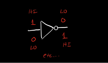
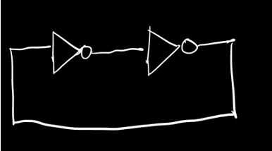
Inverters on their own are kinda boring. It is the "jerk" of circuits, always doing the opposite of what you tell it. However, that simple action, when linked together in feedback loops with other devices doing the same thing, can lead to very interesting behaviors as shown in the figure below. Certain configurations can result in stable circuits and other configurations can result in unstable circuits.
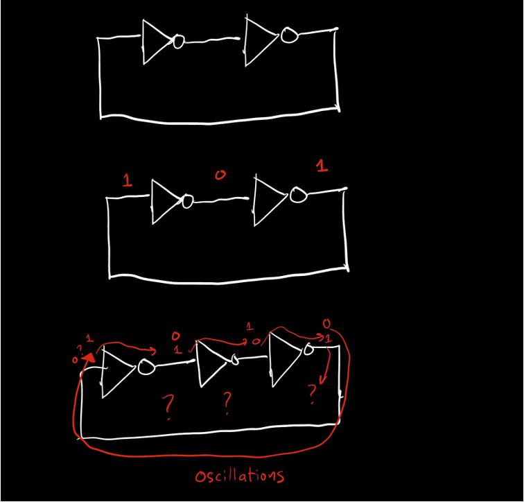
Early inverter-chain circuits were largely concerned with the two inverters. When driving eachother directly, you'd end up with a stable circuit that could hold a value. When you alternatively added high-pass filters in your chain, like shown below, you could get unstable circuits, but, importantly, these circuits could be predictably unstable resulting some nice oscillations based on the values of the C and the R which you choose:
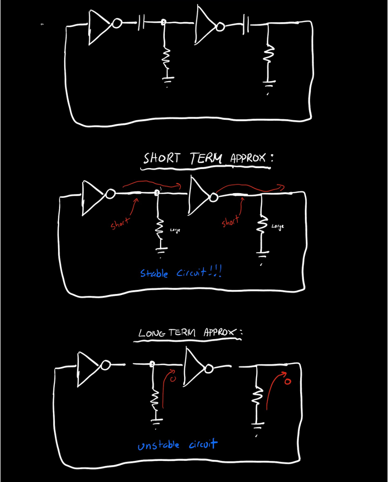
We're skipping a lot of math here in there interest of brevity, but the unstable or "astable" inverter chain, is the first circuit we'll build. This was developed/discovered around 1919.
Let's build this.
Triodes Form an Oscillator
For the first circuit you'll be using the same tube from Lab 2, the 6J6.
- Pins 3 and 4 are the filament. This must be at 6.3V.
- Pin 7 is the cathode, common to both triodes.
- Pins 1 and 6 control the plate and grid, respectively of one triode.
- Pins 2 and 5 control the plate and grid, respectively of the other triode.
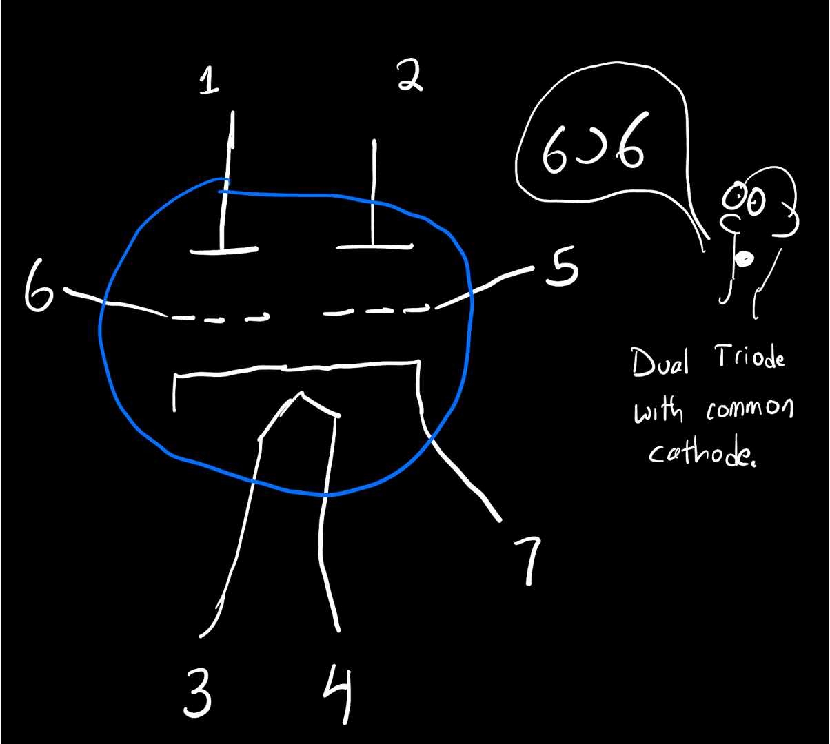
Here's the datasheet for the 6J6
Our Abraham Bloch astable multivibrator will use fixed capacitors (which you can swap out as desired) and variable resistors for setting the gain feedback and bias point between the two triodes. The core of our circuit is shown below:
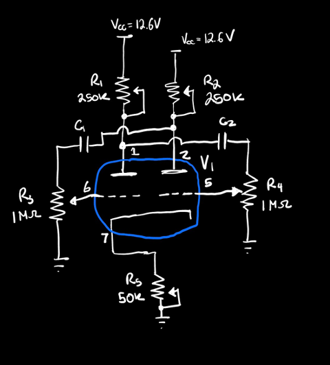
- Pots R1 and R2 set the gain on each stage. Start out with these being about in their center.
- Pots R3 and R4 set the inverter-to-inverter drive strength (which is effectively the feedback of the circuit). You can also start out with these set to be about in their center.
- Pot R5 sets the bias point of this triode. Put in the middle. You may also want to put a 10 uF cap in parallel with it.
- Capacitors C1 and C2 can be anything, but should be roughly the same. Start out with them being 1 uF.
This circuit can oscillate when tuned properly, but using its oscillation is very tough since the tubes are in starvation mode and will have very little output energy to spare to do anything useful. Instead what we'll do is tap the output of one inverter and feed it into the input of a second 6J6 used as a standard amplifier. We'll use this tube to drive one of two loads:
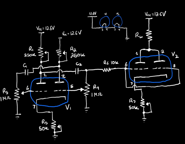
Depending on what you want to do with your oscillations you have two types of loads to drive.
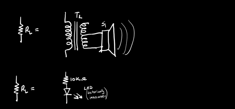
For low-frequency oscillations (on the order of a few Hz), a light is the best way to demonstrate it. Make RL be a 10K resistor driving a (historically anachronistic) red LED like shown below. The full oscillator with C1 and C2 being about 1 uF should get you some low-frequency flashing (though of course make sure you use the oscilloscope to tune). The result should be similar to below:
For higher frequencies, swap C1 and C2 for something like a few nF (thus shortening the time constants of the in-line RC high pass filters making the circuit change state much more quickly). Replace the LED and resistor with a audio transformer (like from lab 02) and a speaker. Retune the circuit (again using the oscilloscope to aid in the endeavor) and get some nice audio like shown below:
Nice. Now instead of having a unstable circuit which oscillates, can we have a stable circuit? Something that holds a value for us? Let's move on.
Bistable Multivibrator
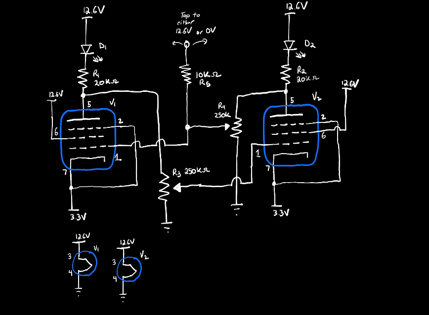
Previously we built a circuit that is astable and continuously changes its state. The presence of the high pass filters is what caused the circuit to be unstable. If we remove them and build a circuit like this one...
...It should be possible to get a circuit that holds its value (and be bistable, existing in one of two states).
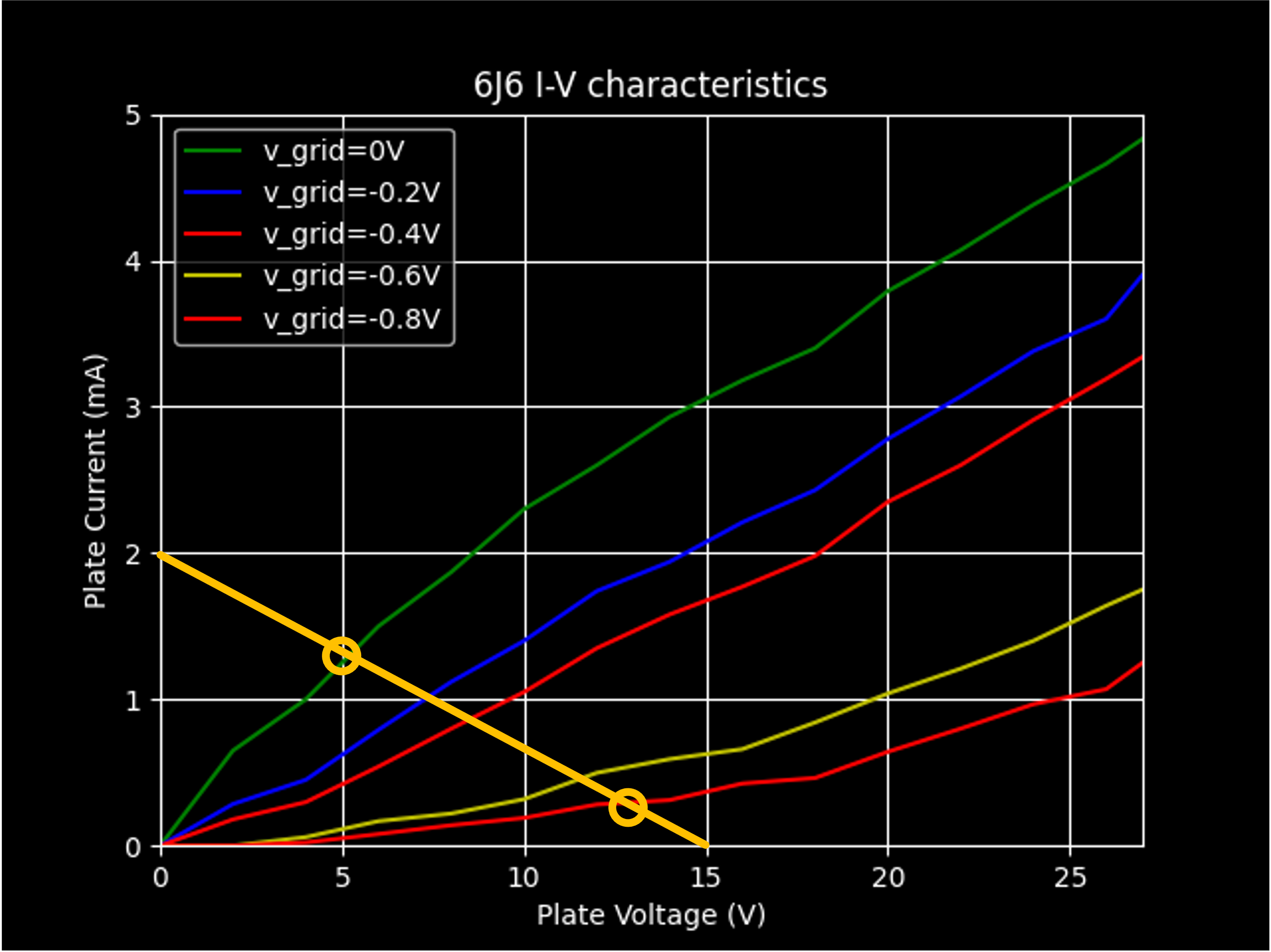
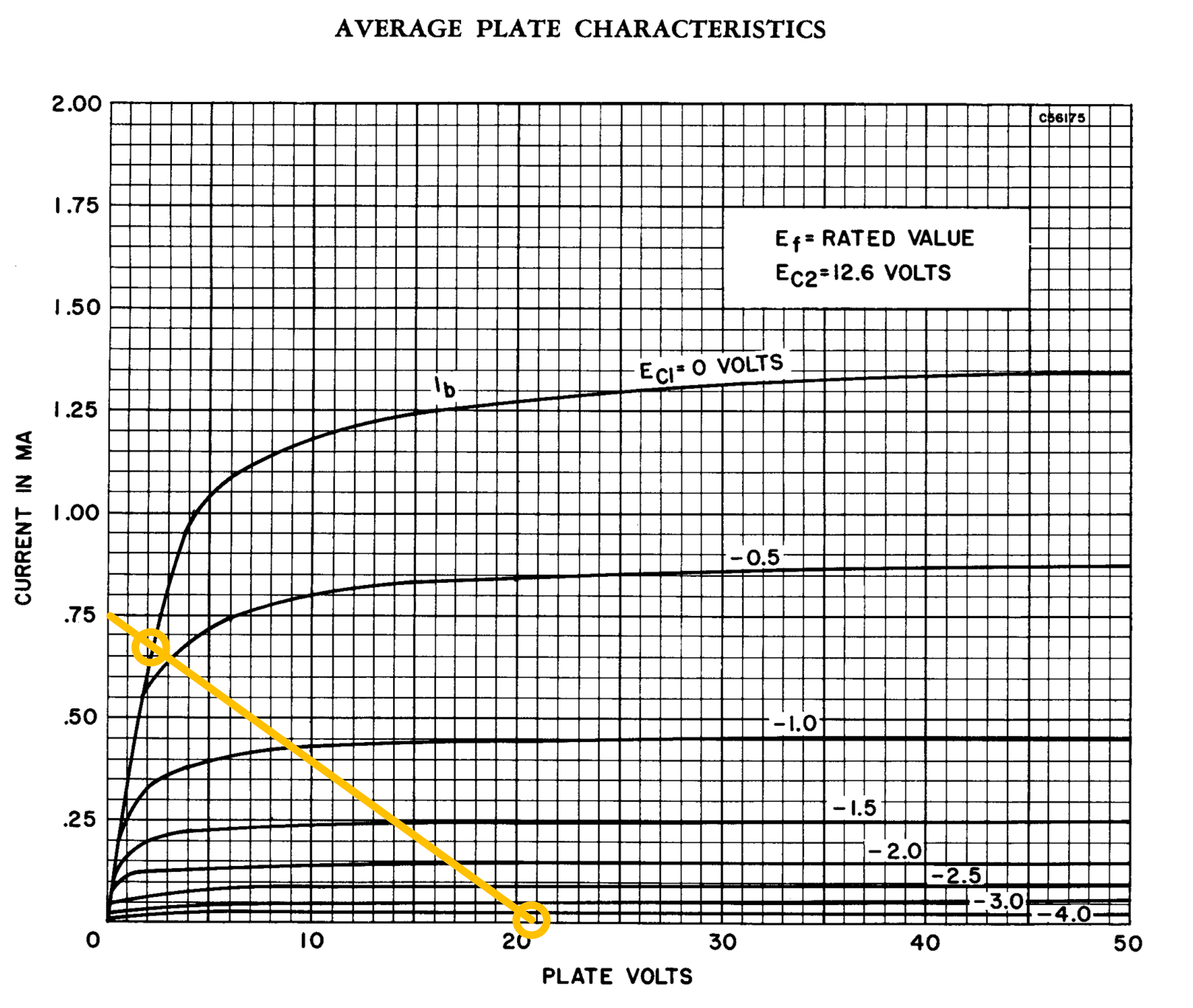
Is it as simple as pulling the capacitors out of our previous circuit? Unfortunately no (at least for our class). Consider the 6J6 IV curve:
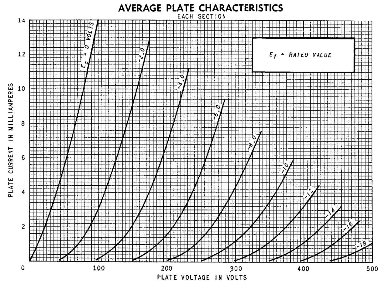
For the purpose of building a digital inverter, we really, really need the ability to hop the active device (our triode) between two vastly different states of being. In particular in a circuit like a multivibrator we want one state being highly-conductive (a near-vertical line in its IV-curve) and one state being highly-non-conductive (a near-horizontal, low line in its IV-curve). We've been very obsessed with having our vacuum tubes give gain in this class, and while that's important what we want now is gain and non-linearity in its behavior (as a function of the grid voltage). If we mount a load-line (from a bias resistor) on our 6J6 IV curve you can see that over large voltages, you can kinda get that behavior (consider the two extreme operating points circled)
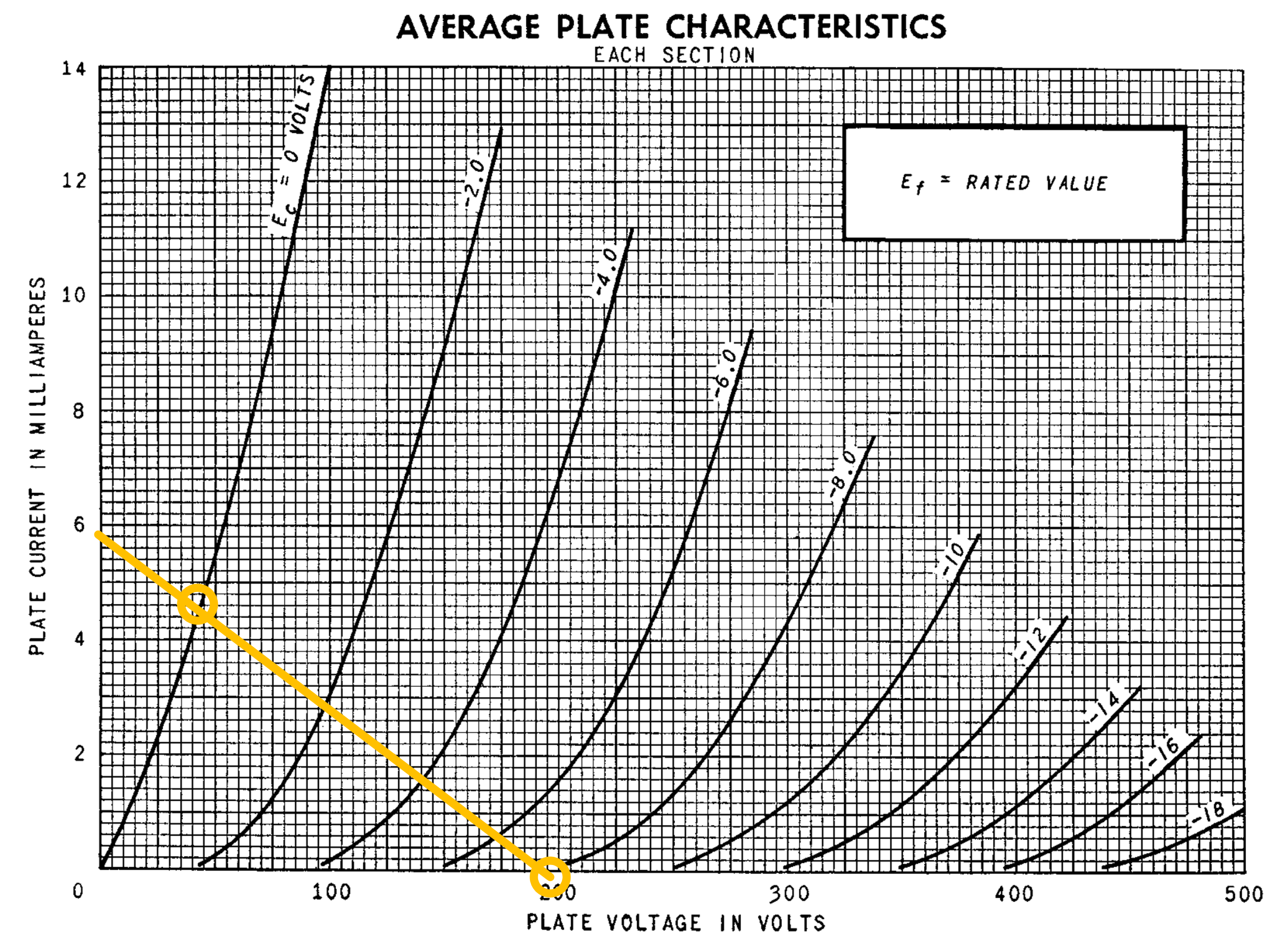
But we can't (because we run our tubes at low voltage) do that. Check that a load line our low-voltage IV-curve for the 6J6: You'll see that from one extreme to the other the nature of the triode doesn't change that much...it just goes from one resistor like state to another of less conductivity...no drastic ON/OFF changes.
Interestingly, the 6J6 triode can be run at positive grid voltage and get quite drastic ON/OFF changes, as shown in the additional curves in its data sheet. But at positive grid voltages, the grid current starts to get as large or larger than the plate current in starvation mode so it won't work (since the thing driving the grid in a circuit like this is another triode).
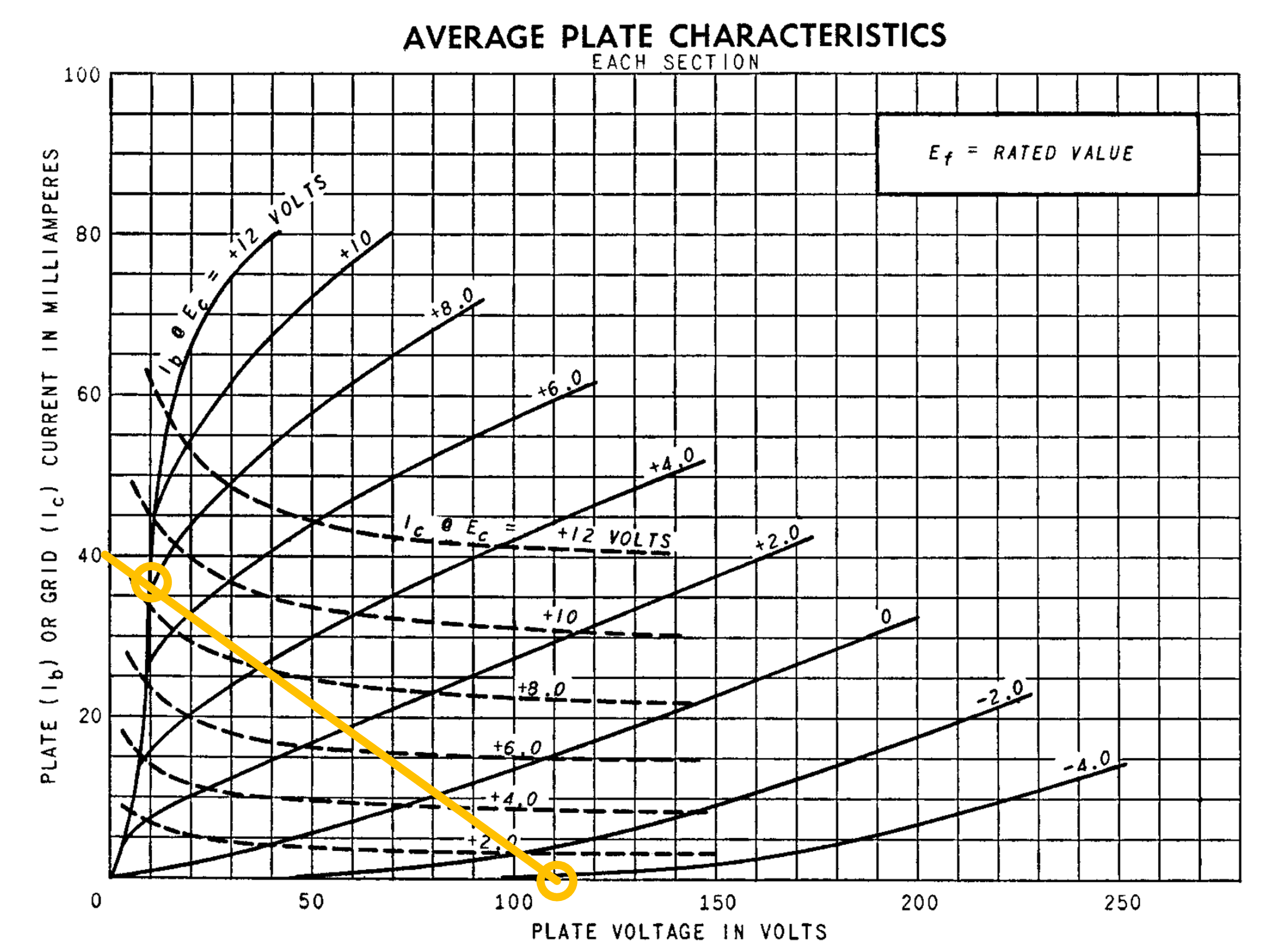
Basically, what I'm trying to say here, is that if we could run our tubes at full voltage, we could actually use the 6J6 dual triode in a bistable format/variant from above. Believe it or not, this was one of the 6J6's raison d'etre, for they formed the flipflops in quite a few early IBM computers. But it just won't work here. In my experimenting you need to get up to at least 60V for it to work reliably, and we're not going to do that.
Instead we'll use it as an opportunity to use a special low-voltage pentode tube, the 12AC6!
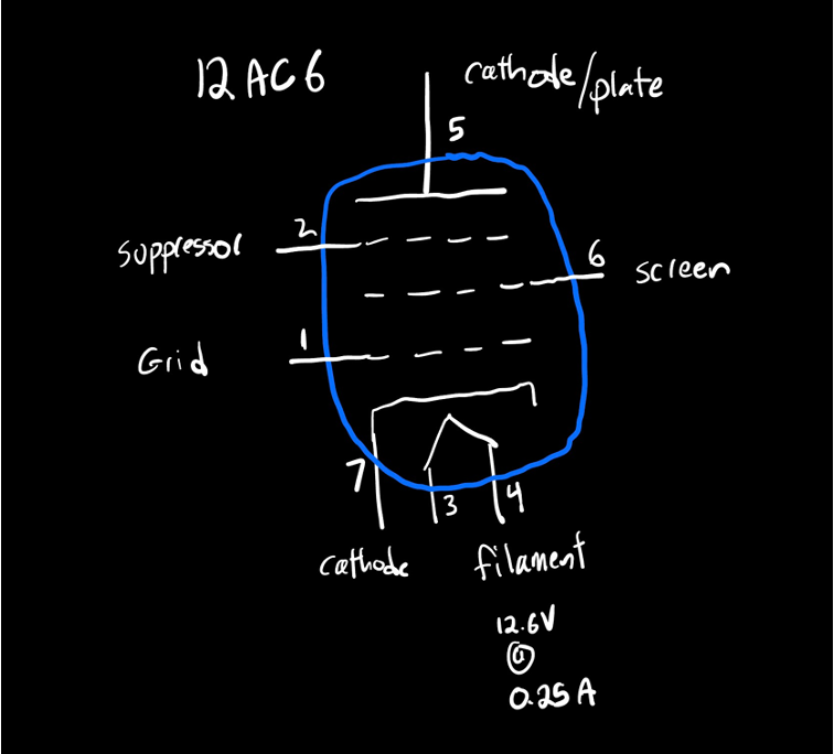
The data sheet for the 12AC6 can be found here. Very importantly, this type of pentode, while providing pentode-quality IV curves for us, does so at low, safe voltages. I can take its IV curve directly from the data sheet and just looking at it you can see that within a range of safe voltage we can have the plate-cathode terminals exhibit drastically different behaviors (and give us that on/off nature).
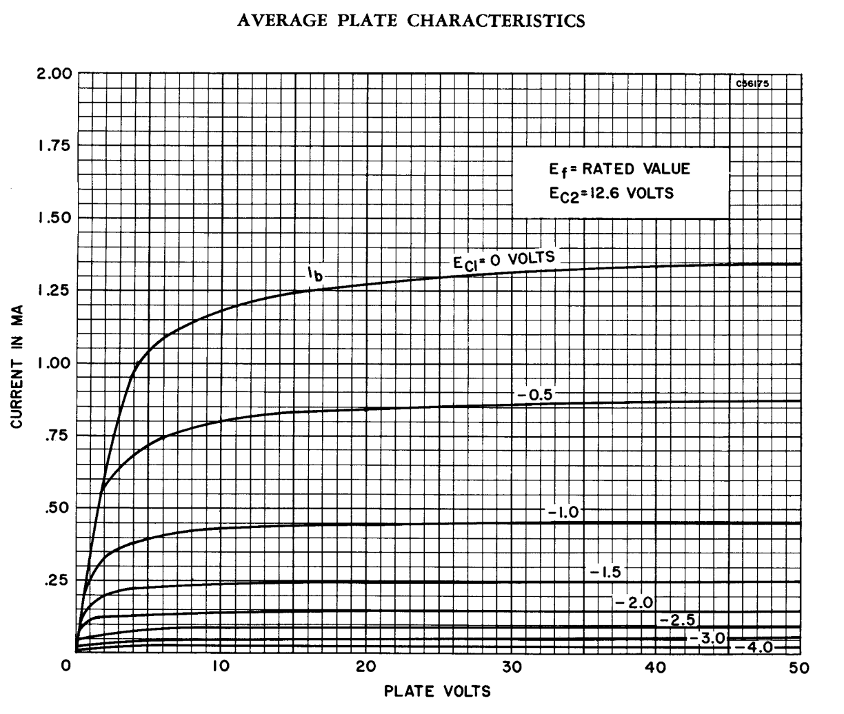
Putting a reasonable load-line on this IV curve reveals that at the extrema, we can very clearly get an "ON" and "OFF" behavior:
OK so how can we take advantage of this? Well we'll grab two 12AC6 tubes. They are also 7 pin packages, but since they are pentodes they have more electrodes and you can only fit one inside the tube. So you'll need two tubes. Put your two 6J6 triodes back in the big box and replace the two sockets with 12AC6 pentodes. Note, I've marked them with red nail polish to make sure you don't mix them up (they have incompatible heater ratings so mixing them up can burn out the tubes).
The filament voltage on these tubes is 12.6V. We'll run our entire circuit on 12.6V so instead of stringing the filaments in series, we'll do it in parallel. Build the circuit below. Use a second power supply set to 3.3V to bias the cathode of the two pentodes at a positive voltage. For the two feedback pots set them to about 40% pointint go ground, though you'll likely need to mess with that a bit. Use the same red LEDs from the earlier part.
Once built, you'll need to tune your circuit so that it shows clear bistable behavior. This can be a bit tricky, but once achieved, what should happen is at power up, the circuit will "come up" as the heaters heat up with both sides rising in voltage initially, but soon the circuit will realize both sides of the pentode amplifier outputs can't be high so one side will win out as shown in the video below:
Now the super important part....at the grid of one pentode, have a 10K resistor dangling off. In the schematic this is R5 in the schematic. You should be able to tap one side of that resistor to 12.6V and set the circuit in a mode where one side is high and the other is low. The wire does not need to stay at 12.6V though. The circuit should sit in that state and hold its position. Then if you were to come in and tap that wire to ground, the circuit will flip state and hold its value after you remove the wire:
At first, this behavior might seem underwhelming, but what we have here is a circuit that can remember. This is monumental. Previously all our circuits are "stateless" in a sense, but the oscillator from earlier, and more importantly this circuit actually display values not only based on current inputs but also past inputs. This is the beginning of the astronomical in scale complexity at the heart of modern computers. The ability to remember one yes/no or high/low value cannot be understated in terms of its importance.