Lab 2
Intro to Triodes
Here's the ampifier playing a song from Dare by the Human League, perhaps best known for their hit "Don't You Want Me" off this album:
The Tube (6J6)
We'll be using the 6J6. Three of them to be exact. This is a 7 pin "miniature" tube, made of all glass. The data sheet is here. It is comprised of two triodes that share a common cathode. It was originally intended for RF work during the Second World War, but I believe found a second "life" in some early vacuum tube computers. They made them in large volume and since it isn't particularly good for audio, one of the only remaining markets for tubes with any sort of volume, its market rate is very cheap. The tube's pinout is shown below. Note:
- Pins 3 and 4 are the filament. This must be at 6.3V.
- Pin 7 is the cathode, common to both triodes.
- Pins 1 and 6 control the plate and grid, respectively of one triode.
- Pins 2 and 5 control the plate and grid, respectively of the other triode.
In case it isn't clear, the two triodes can be controlled separately, however the fact that they share a cathode does limit how "separate" they can be (certain circuits and topologies aren't possible). Still, there's a lot that can be done!
The data sheet for this tube, like most tubes, gives juicy details and shows its behavior over several hundred volts.
That's great and all, but for our class, we're staying much lower so would benefit from a zoomed-in plot. Thankfully, I'm a caring person, so I went through and took some data and that helped me get a feel for this tube's behavior in this area of operation. Look. At. That.
To make the tubes easier to work with in the breadboard, I fabbed and soldered up some nifty little tube breakout boards with the pins labeled and everything. There's a box of them up front.
The System
The audio amplifier is broken down into three stages, each one being made of a tube and supporting electronics. The three tubes will need to have their filaments powered, with each requiring 6.3V and 0.45 A of current. To achieve this we'll run them in series (as was often done in tube sets1). We have three tubes so we'll set our power supply at 18.9V. Set the current limit to 0.5A. We'll also use this power supply for the actual "signal" part of the circuit too.
As far as signal processing goes, the circuit has three parts:
- A "preamplifier" largely concerned with making a larger voltage to drive subsequent stages.
- A "phase splitter" that converts the single-ended audio signal into a differential signal on two wires 180 degrees out of phase with one another.
- A "push-pull" amplifier that uses the complementary audio signal to drive a speaker at moderate volumes.
Let's go through each stage. Refer back to lecture for some circuit component purposes, though I'll try to cover them as best I can.
The Preamplifier
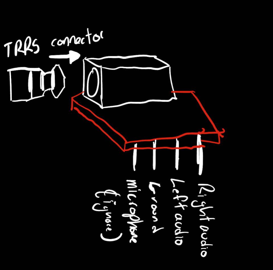
The preamplifier will take in audio from a standard 3.5 mm TRS connector. We will merge the audio signals of the left and right audio channels into one signal (A mono amplifier). There are cables and a little red TRS plug board on the table that looks like the following:
The audio will be the input to a tube stage shown below. It is very simple. It is actually a "one-triode" circuit. We merge our two triodes here by running their grids and plates together. While doing this with a transistor is a bit icky, tubes like this will be fine. Treat it as one single triode, just with twice the current.
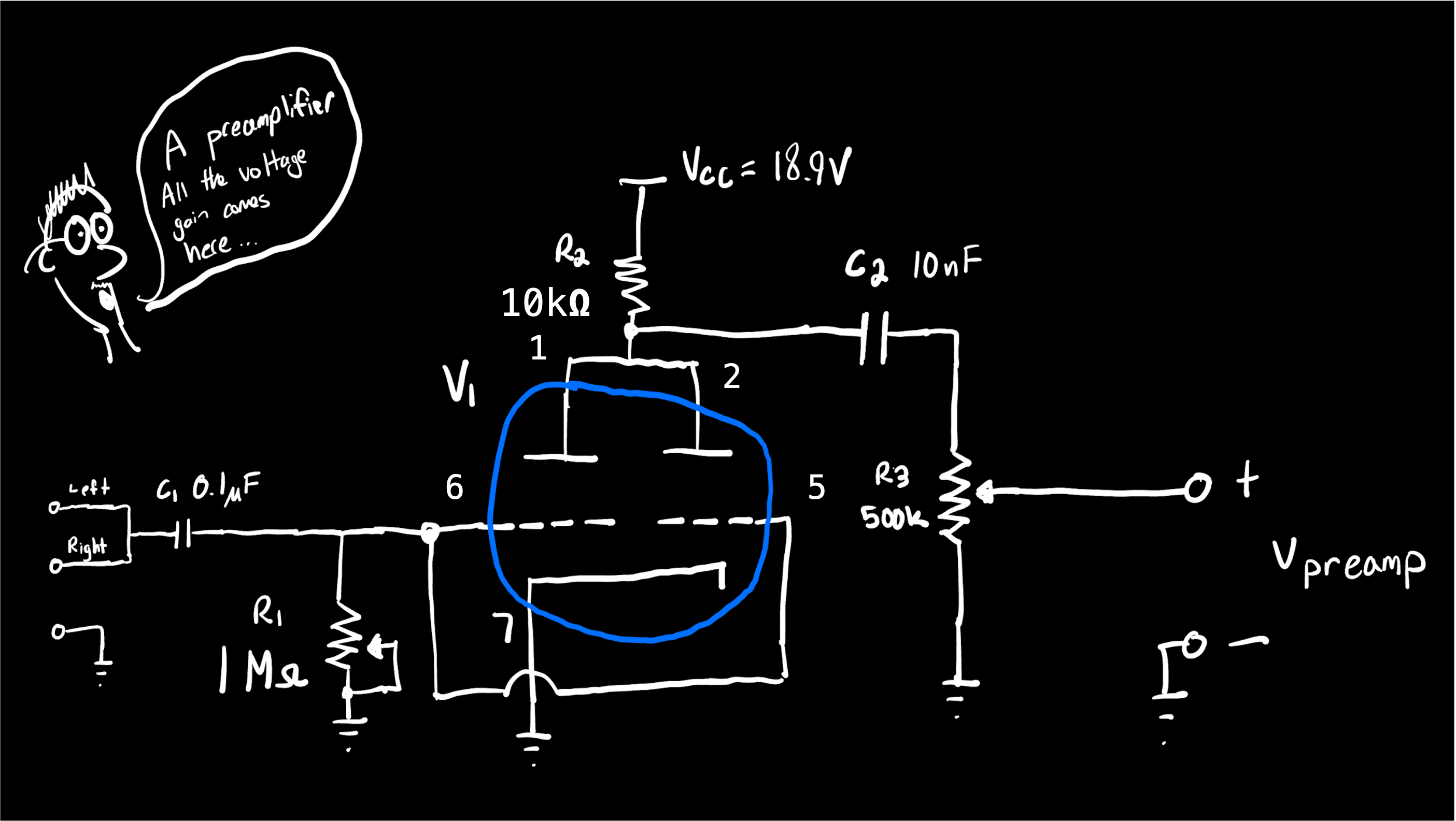
Like all amplifier circuits with tubes (or transistors) we need to "position" the circuit in the electrical space and then operate around that point. We call this action "biasing" and this involves picking resistors and other components so that the device lives in a particular part of its I-V space.
There's no "right" answer here. There are plenty of wrong ones. In messing with the I-V and some load line analysis, I settled on about 10K. This seems fine, though you can change. As for the grid bias, there are choices to be made as well. Somewhere in the -0.2V to -0.3 V space seems to be best and give the opportunity for the most linear and largest gain. With all that said, these I-V curves are awful from this tube and I can see why these weren't meant for audio. Oh well onward and upward.
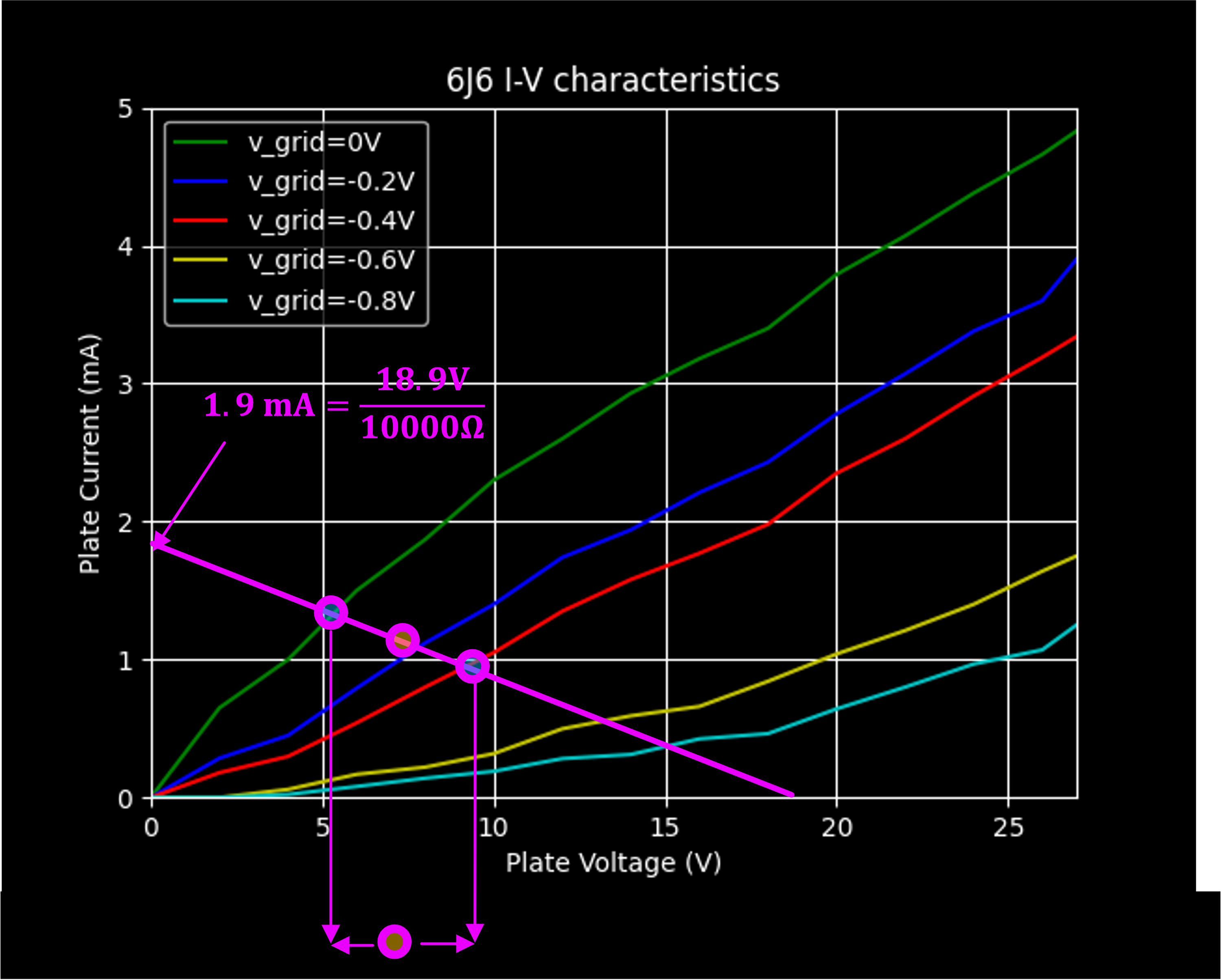
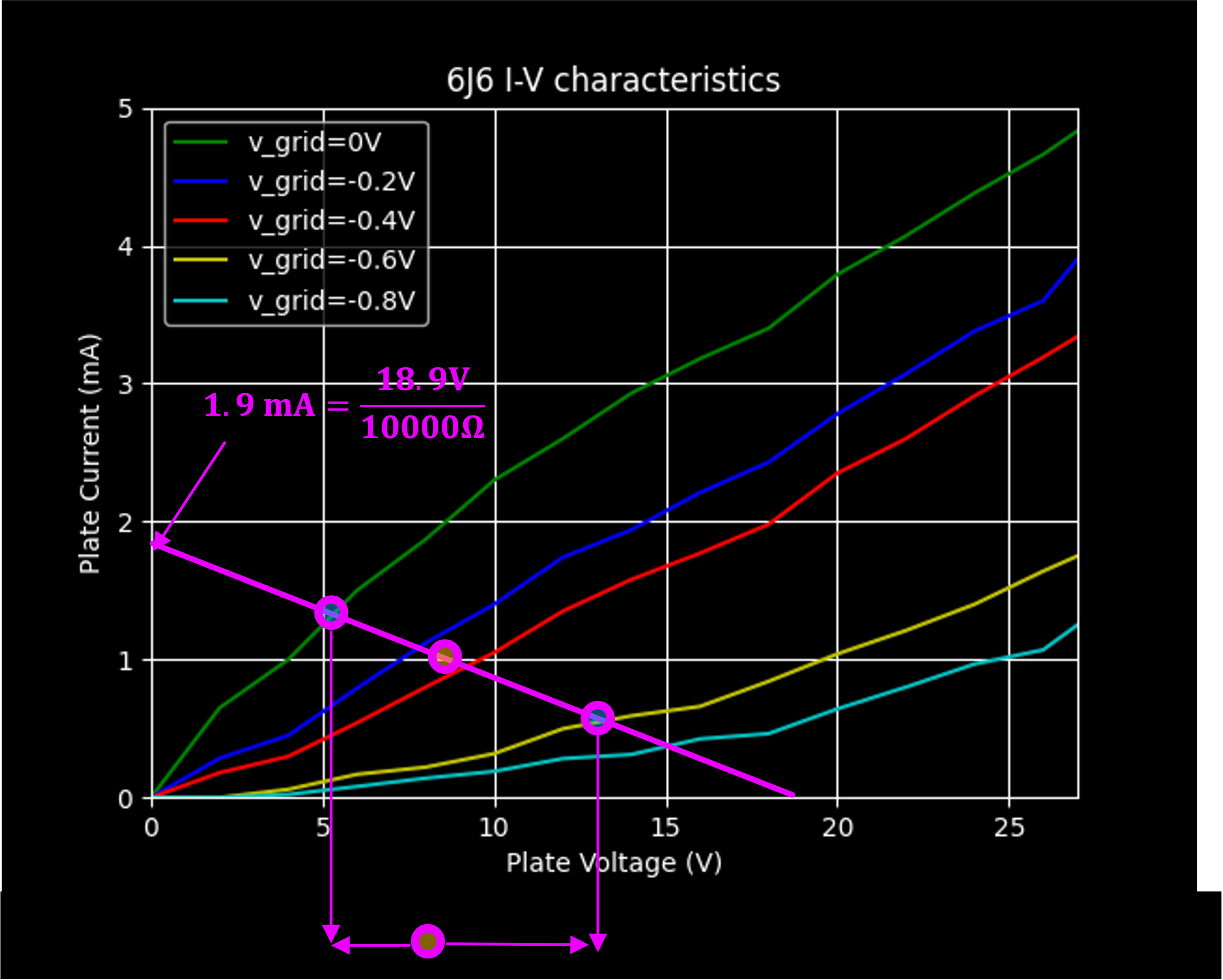
The two resistors position this circuit at the point(s) highlighed above.
- R_2 is your bias resistor which sets your gain and operation point (mostly). It is the inverse slope of that line above (10K Ohms). Could have picked others to varying degrees of success.
- R_1 is a grid-leakage resistor (potentiometer set up as variable resistor) and sets the grid voltage. You should use a oscilloscope to watch how your signals change in order to set this. Too high or too low and your. This value does need to be large, you'll see, and it can also drift a bit over time so you may need to periodically adjust it (there's a reason this wasn't a widely used bias technique).
The input and output capacitors are for DC-blocking, making our bias job easier. The output potentiometer is a variable voltage divider acting as a volume control for us.
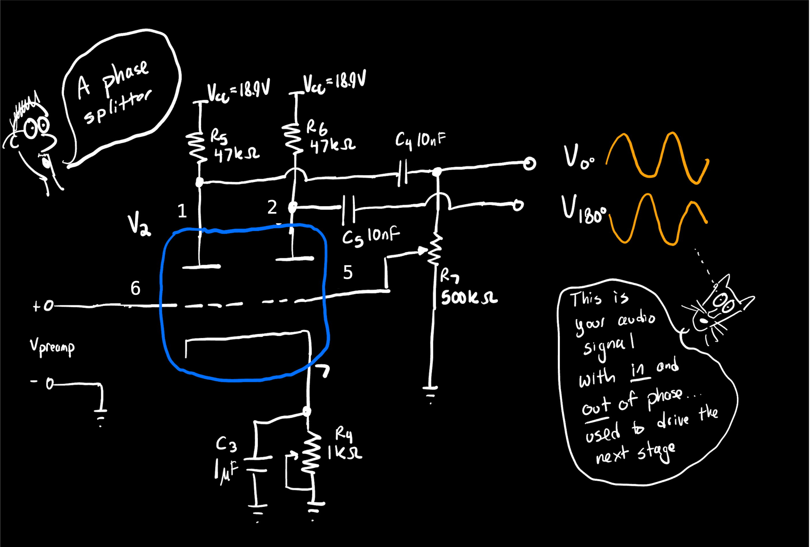
The Phase Splitter
The output of the preamplifier will then be fed into a phase-splitter. The job of this circuit is to basically make identical, but out of phase variants of the input signal. It really doesn't need to have any gain involved. The signal comes into the left triode, its output is sampled at pin 6. It is used as one output, however it is also used as an internal feedback input to the other triode. The amount that is fed back will need to be trimmed in real-time with pot R7. You want to (using the scope) make sure the two output signals are about balanced in size (but opposite in phase).
R4 biases the two triodes using "cathode biasing". C3 removes the cathode bias at AC so the tube doesn't have negative feedback kill off its gain when it matters most. You may want to try adding a grid leak resistor pin 1 for this part. The resistors R5 and R6 also dictate the bias of the two stagse. These should be played with. I actually thought a lower value would workd well, but a higher value seems to sound better...though that doesn't mean the signal is actually "better"...it just might be distorting in a more pleasant way.
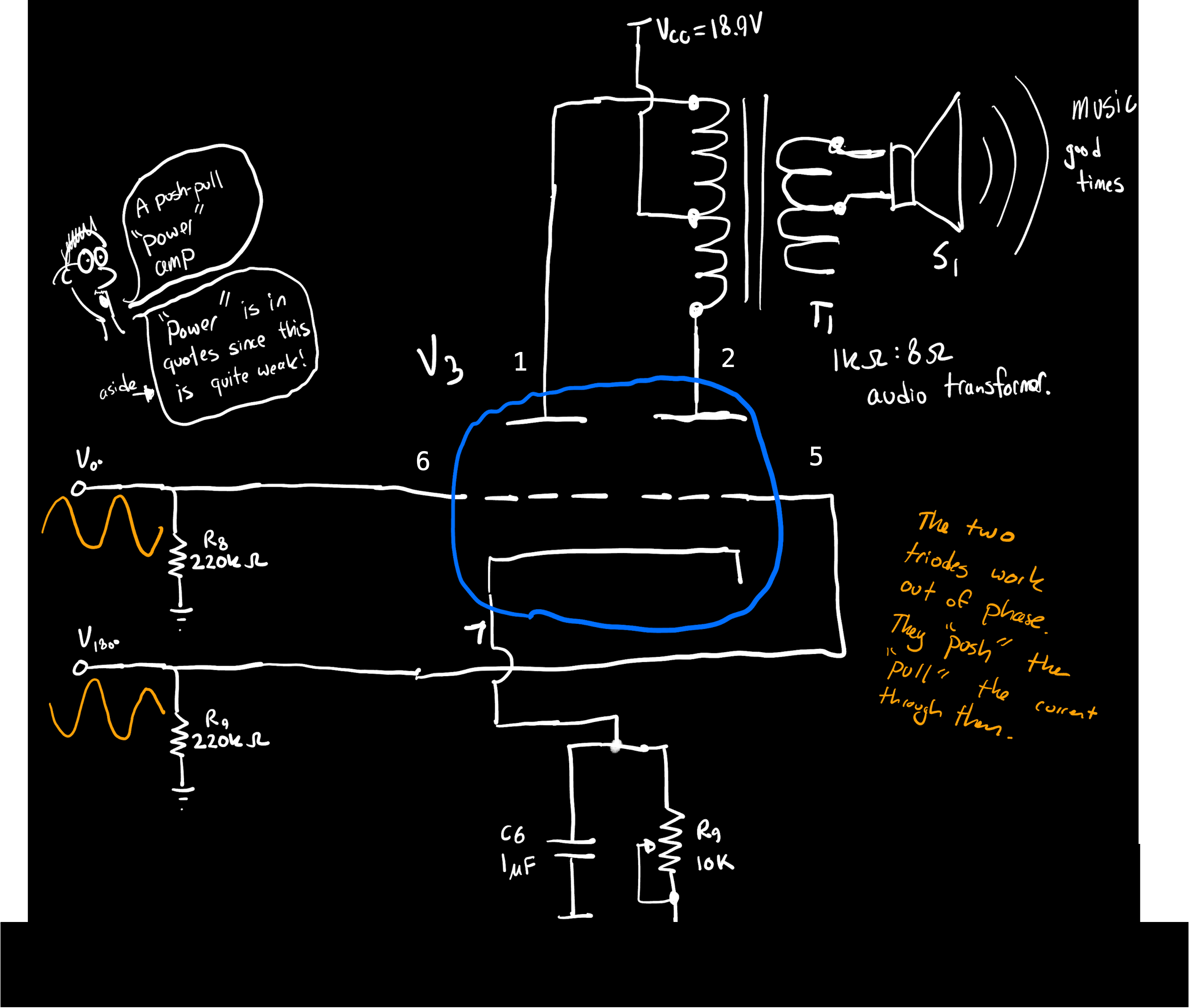
The Power Amplifier
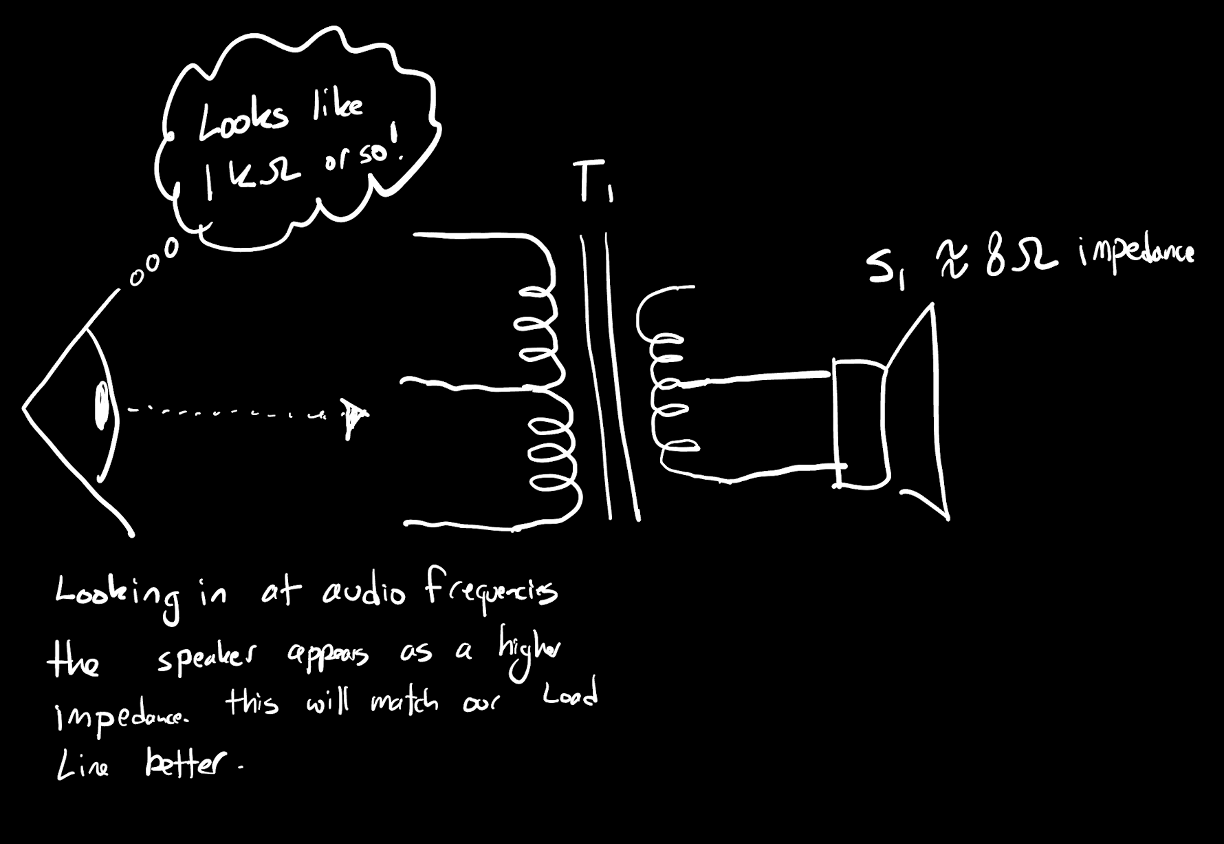
The final stage is a push-pull amplifier. We'll drive two triodes with the complementary phase signals of the previous part. These triodes will feed energy into a speaker. The speaker is a load like any other, however, and we need to be conscious of how well it is matched to circuit driving it. In this case the speaker's very low resistance provides an awful load line to engineer around. Compared to a nice load line like 1000 Ohms, it looks just plain bad:
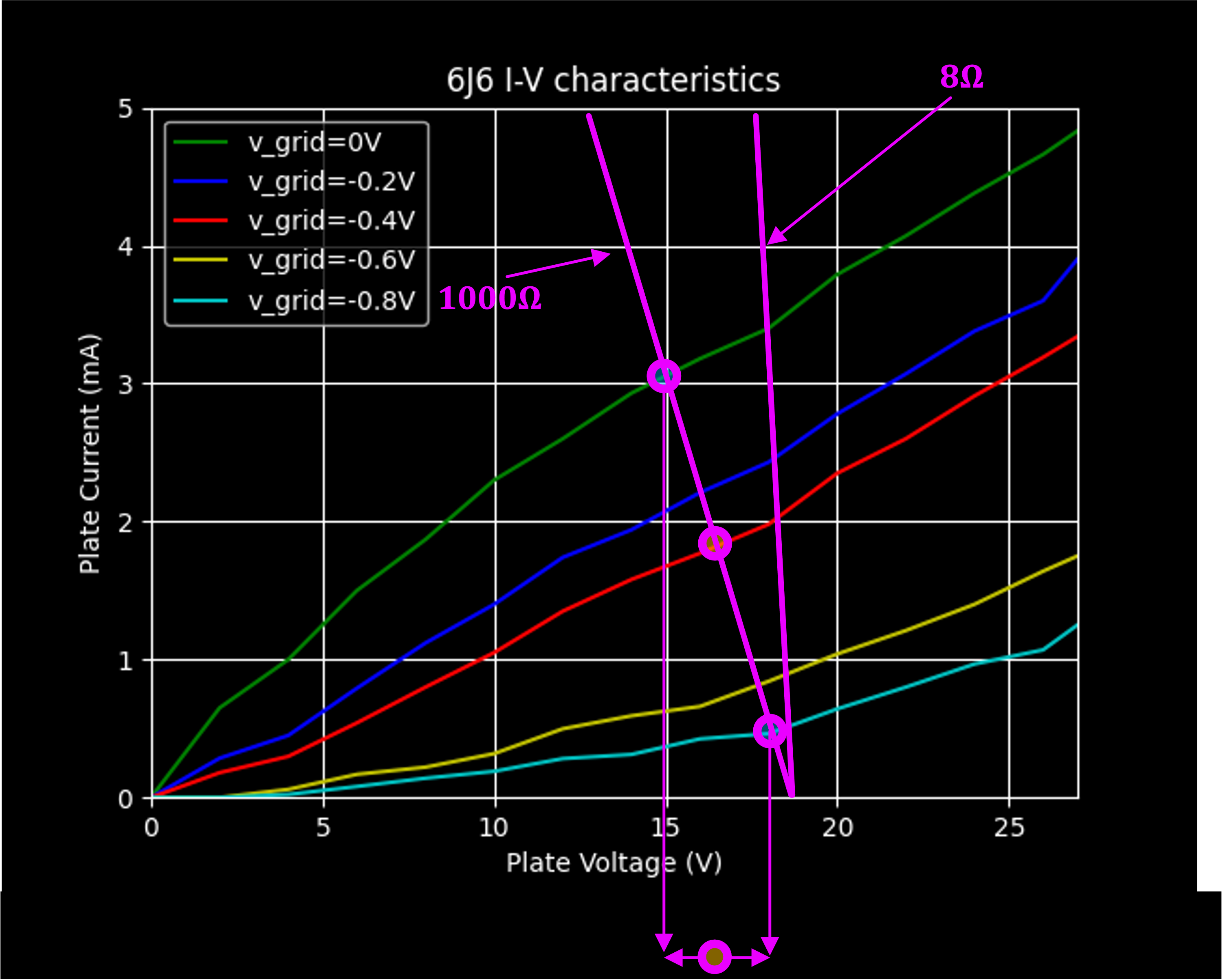
Thankfully, a transformer can help with this. We have some 8:1000 transformers, which means they can transform the the 8 ohm speaker impedance into about 1000 Ohms at audio frequencies. They do this using this equation discussed in lecture four:
The circuit has a bit of grid leakage bias (feel free to change it) and some cathode biasing in place (again feel free to change these values). Note the transformer's primary side (marked with a "P") is the one wired towards the tubes. The center tap on the primary goes to 18.9V. The two sides on the primary go to each plate. On the secondary side, have the speaker go from the center tap to one side. This will maximize power delivered.
Points of Adjustment
Pretty much every component in this design can be varied. Everything that is a potentiometer is meant to be tuned while the system is running in order to find operation. I would suggest positioning all potentiometers in the middle of their range and then use scope probes to measure the signal throughout the circuit.
- Put a scope probe at the input of the preamp (right at the grid), one at the output of the preamp, and one at the preamp. Adjust R1 until the bias is negative enough and you're getting a good signal at the output. Note you may want to consider swapping R2 with a 50 K pot and then also varying that to find a nice sweet spot for your gain.
- With good signal coming out of the preamp, set up your probes so you have:
- A probe at the input (right after the input volume pot R3)
- A probe at the output of the "in-phase" component to the right of C4)
- A probe at the output of the "out-of-phase" component to the right of C5
- A probe at the cathode of the phase-splitter tube
- Proceed to adjust R4 to position the cathode bias and then use R7 to balance the the phase so that the output at C4 and C5 is about equal in amplitude.
- Finally:
- Keep two probes on the in/out-of-phase signals which are the inputs to the push-pull amplifier
- Move a probe to one side of the speaker and trim R9 until you get a signal.
You should be able to get some decent sound out. It will not be crazy loud. It will also be distorted. But you'll have audio and it will have come from the gain that the tubes are giving you.
Things to Add
To be fair, every passive component in this circuit could be modified. Feel free to try changing things. I tried to remove as many parts as possible and still have a reasonably working circuit. I think even more could be pulled. Bias resistors R8 and R9 could probably go. R9 could be changed. Pretty much everything could be varied. That's ok. Feel free to experiment!
Footnotes
1in fact, many tubes that were expected to work together would have filament voltages that would add up to common voltages...a classic example is the "All American Five" Radio, a set with five tubes. The five tubes would be a 12 V converter, 12 V IF amp, 12 V detector, 50 V power amplifier and 35 V rectifier tube, with all voltages summing to about 120 V, which is about at mains voltage.