Lab 01a
Electromechanical Detection and Amplification
We're not going to do labs like you'd have in 6.08/901 or 6.002/200 or 6.111/205. There are no checkoffs or coding questions. They will tend to be some schematics, descriptions, instructions, and then it is up to you. Parts should be on the center table in our lab area mostly labeled. I'm more than happy to help if I'm around and free or doing office hours! If you see another student working on it, bug them if you need help or if you want to offer help! The point of these labs is to appreciate electrical phenomena.
The Predicament
The appearance of the vacuum tube in the first few years of the twentieth century yielded a device that could provide reliable amplification and which could also provide reliable non-linearity. Both of these characteristics were very desirable for lots of reasons. Amplification was important because signals inevitably lose strength as they are handed from one party to another (or one circuit to another). Nonlinearity was important since it allowed the ability to do things like demodulate and perform higher-order operations with the circuits...this is exactly the same reason you need some sort of non-linearity in your neural nets for them to do anything useful beyond linear classification.
However, tubes weren't "invented" until ~1906 and it took another ten years for them to become widely available in production (~1920). Prior to this, society still accomplished a lot (telegraphy, telephony, radio, primitive control theory), but it was just mostly done using electromechanical means (and some other early things...see next lab). To understand why vacuum tubes and semiconductors were such a critical development, we need to grok the limitations of electromagnetic/mechanical systems. We'll do that in this first (quick) lab. We'll look at how detection and amplification of signals could be done using just electromagnetic devices.
Inductors
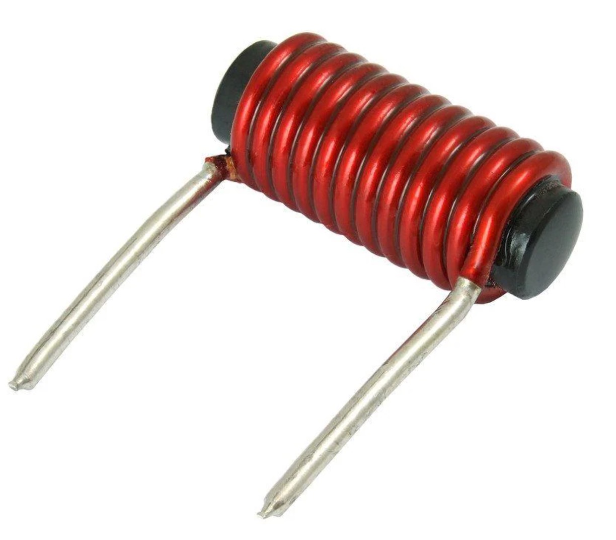
For quite a few decades, most electrical equipment was reliant on electromagnetic sensors and actuators. At the core of these devices were coils, which we usually call "inductors" in circuit land. An inductor might look like this:
Schematically a coil/inductor looks like this:

or this:

An inductor is nothing more than wire run in a certain number of loops. It is a convenient and reliable means of transforming an electrical current into a magnetic field (and you can also do vice versa, making a magnetic field induce a current). Sometimes, the coil will have a chunk of material through its core. This is done because it can greatly increase the amount of inductance you can get per unit volume (the inductor in the first figure above is a cored inductor, for example). In that case you'll might see the coil drawn like this if it matters:

So what do you do with a coil? Well there's a few things. Ignoring its electrical properties that are beneficial for things like filtering, you usually used the induced magnetic field to move things.
Solenoid
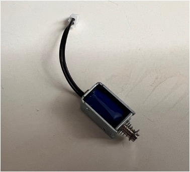
One thing you can make given a coil is a solenoid. A solenoid is basically a device with a moveable, ferrous metalic core inside the coil. Sometimes there is a mechanical spring return on it as well. Application of current to the coil leads to a magnetic field, which can then cause the moveable core to adjust its position. Removal of that current will cause the core to adjust back (often with the assistance of a return spring). This change in position can be used to useful things...perhaps move something mechanically, or ring a bell, or punch paper, or many other things.
Grab one of the small solenoids in lab. They look like this:
Schematically we'll use the symbol of a motor to represent this solenoid.

In more detail a solenoid can be modeled electrically with the following circuit. For the solenoid we have in class, its approximate values are shown:

Hook this solenoid up to one of the power supplies and figure out how much voltage/current you need to actuate it. In my experiments, I found out it needs about ~3V and ~0.8A, but your solenoid could be different. That means in order to actuate properly to an incoming signal, the system must be capable of providing about 3W of power to the solenoid. Let's keep that in mind.
Solenoids as Sensors
Now let's say we wanted to use this solenoid as a sensor to ring a bell on a telegraph line. The fact that the solenoid needs 3W of power to actuate is going to be a problem. In such a situation, a distant battery bank would be providing a current in a closed loop that exists over many miles. Parasitic resistances/losses throughout the entire network would mean that practically speaking very little current would be flowing through entire circuit. This could potentially be fixed by increasing the battery voltage in the system, but this leads to more loss and can become ver inefficient. The amount of power left to extract by this solenoid in the circuit is just going to be insufficient to actuate it.
We can model a distant, weak, incoming signal in lab using the waveform generator on the oscilloscopes. Activate the waveform generator on the oscilloscope and hook it up to the solenoid. Make a ~1Hz square wave signal of a 3V and try to turn on the generator. You should notice that the waveform generator will not turn on. The waveform generator lacks the power to drive the Solenoid directly. This is basically the same situation a large-scale communication system would be running into.

How could this be fixed? What we need is an amplifying device. Something that can modulate a local (to the solenoid) large energy source based on a small signal (that which is available from the telegraph signal). To achieve this we need another device that "uses" less power. One way to do this is to make a coil that makes a larger magnetic field for a given amount of current. Making a bigger inductor is as simple as putting more windings of wire around your coil.
A Reed Switch
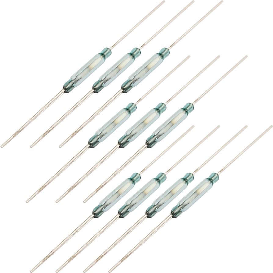
Another thing you could do is have your coil induce less motion mechanically. Part of the reason the solenoid needs 1.5W is because the piston that it is moving is quite large. If you had to move a very, very small piston a very, very small distance, you could get away needing to induce much less magnetic field. That is what a reed switch let's us do. They look like this:
The symbol for a reed switch usually looks something like this:

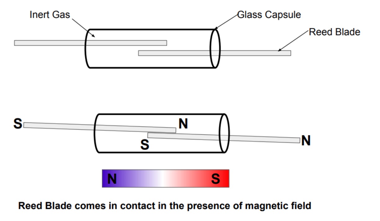
A reed switch is comprised of a pair of contacts that have just a little bit of overlap and are separated by just a little bit of a gap. The pieces of metal have a bit of flex in them. In their normal state, they do not touch, and therefore from one contact to the other there is no conduction. However if a small magnetic field is exposed along the axis of reed switch, the two flexible contacts straighten out and make contact. In the process, from one electrode to another, you can get conduction.
I have some reed switches in class. Feel free to grab one and hook it up to the ohm/continuity setting on one of the multimeters. Normally you'll see them open, but if you put a magnet near it, it'll close (and the meter will read 0 Ohms/short). Very cool. Believe it or not, reed switches and magnets are still used to this day in some low-cost door/window sensors (though they are getting to supplanted by devices that rely on the Hall Effect more and more).
Relay
So we have a thing that will make potentially meaningful mechanical movement given a small magnetic field (reed switch). We can put that reed switch close to our higher-inductance (and therefore higher magnetic field) coil like shown below:

Now, if you'd like, I actually do have individual high-value inductors and reed switches if you'd like to make your own detector from scratch. There is a sense of achievement with that. If you position the inductor so that its axis is in-line, but adjacent, with that of the reed switch you can cause the reed switch to open/close based off the application of current to the inductor.
For those who don't want to do that (no shame), you can take advantage of the fact that the device we're describing has already been invented and optimized to a huge amount. We usually call this device a relay. It looks like this:
You can have different types of relays, but the simplest is a Single-Pole-Single-Throw (SPST) relay. Its schematic symbol looks like this:

We have a pile of them on PCBs for easy breakout (though they will require wires to be soldered to them).
The Circuit
With a relay, we can now build the following circuit. Drive the +/- input signal on the relay with the function generator from your oscilloscope. Start with a 3V 1Hz square wave signal (watch the polarity on the input signal since there is a flyback diode). You should start to hear the relay itself clicking on and off as it runs. Take the power supply and use that for the V_{loc} supply in the circuit. Connect the solenoid in series. Once powered up, you should see the solenoid moving in a synchronized fashion with the incoming square wave.

A video of that is shown below. I'm varying the frequency as it runs. See how high of a frequency you can switch your relay before it stops working. You should notice the solenoid (a larger mass) will fail at a lower frequency than the relay itself (with a much lower mass).
The importance of this circuit cannot be understated. If we were to analyze the currents flowing through this circuit, and assuming the source resistor is negligible, the numbers work out to about the following:

Notice that the sensing coil of the relay is using about 3\text{V}\times 0.075\text{A} = 225 \text{ mW}1. The solenoid (now driven at a more proper 5V to let it run more properly, is using 5\text{V}\times 1.25\text{A} = 6.25\text{ W}. This means that a signal that is \frac{6.25}{0.225} \approx 28 times smaller than another signal is controlling it (at least in terms of power). This ability for a smaller signal to modulate a larger signal is what we call Gain. We'd say this circuit has a power gain of 28. This is a big deal.
Relays are actually pretty cool. When designed properly they allow a very small-scale signal to modulate a much larger-scale signal. In the process they are acting as an amplifier. It isn't all sunshine and roses, however. As shown in the video above, their frequency response is awful. Signals above ~100 Hz result in no signal whatsoever. This is because their modulation capabilties rely upon mechanical movement and mechanical movement has to worry about mass/momoentum/drag, etc... You can make better relays, but it is going to be very, very tough to have a good electromechanical device working at anything above 1 kHz.
Another downside of relays is that they are not linear amplifiers. They really can only detect the presence or absence of a signal. They can't detect shades of grade (linearly or othewise) and therefore, would not be suitable to analog-type signals.
Extra Part (Relays Driving Relays Driving...)
We used a relay as an amplifier in the previous section. A small-energy signal was able to modulate a larger flow of energy and in the process, recreate the original signal with more power behind it, enabling detection and usage of the signal. Relays by design are also inherently digital devices. They open/close switches based off of electrical signals. At a fundamental level, this is really all that's needed to create digital logic, the foundation of almost all modern computing. This was not lost on engineers at the time. Consider the circuit shown below:

If we just think about voltages into and out of this circuit in a digital format, we can get a rough pattern of its behavior. Call "low" voltage "0" and "high" voltage "1" and you'll come up with a truth table for this circuit. You'll see the following:
- A=0,B=0: C=1
- A=0,B=1: C=0
- A=1,B=0: C=0
- A=1,B=1: C=0
This pattern, is that of a NOR gate. NOR gates (and their siblings NAND gates) are functionally complete. With them, you can build all other digital logic (both combinational and, if you add in feedback paths, sequential). You may think that would be an exhaustively massive undertaking that is only done theoretically, but that's actually wrong. The entire computer that controlled the Apollo moon lander in 1969 was built using on NOR gates for quality control reasons (of course by then logic was being done with transistors, but the fundamental idea remains the same. We'll get to that in a few weeks). So this is a pretty powerful circuit.
You're welcome to build this circuit above...you can pick any resistor for the pullup, but if you want to be able to have one circuit drive other circuits, you'll need to make sure that resistor is low (like 10 Ohms or something).
Just like neanderthals coexisted with early Homo sapiens for at least several thousand years, relays were widely used in many systems well into the 1950's, even though vacuum tubes were well-established by 1920. Part of this was because relays could be made to function for a very long time whereas vacuum tubes often had limited lifetimes of hundreds or thousands of hours (due to filament burnout and other things). Relays also could run on lower voltages and, amazingly, be more power efficient (relatively speaking for the era, of course).
Interestingly enough, while not the focus of our class, relay-based logic like that shown above was how almost all computers were built up until about the end of the Second World War (~1945). In fact vacuum tubes were really only used heavily in computers for about ten years since the sheer scale of computers made the high failure rates of tubes a really big problem. ENIAC, was the first "full" modern computer and it still had several thosand relays in some of its logic. Prior to that, however, Turing complete computers based solely off of relays were indeed a thing. The Zuse Z3 made by German scientists before and during World War 2, did all of its operations using 2600 relays, which when you think about it, isn't that crazy of a number. The Z3, however had a clock frequency of 5 Hz. That is not a typo. Not 5 GHz or 5MHz or 5kHz...5 Hz. This of course was because of the compounding of the resistor-inductor time constants of all the relays driving one another. Pretty cool.
After society collapses and you need to rebuild from scratch, relay-based logic will probably be your best bet to getting back to a functioning computer. Make a coil and a magnetic-field-based switch. Hook them up like shown above into a NOR topology, repeat several thousand times, and bingo bango bongo, you'll have a computer. The clock rate will be limited by greatly by the relay inductances and parasitic resistances, but at least it will work.