Lab 01b
FM Radio
Overview
In this lab you'll build a very basic FM crystal radio. While the detector is an AM detector, we'll use it in a manner known as "slope-detection" which allows us to coarsely convert frequency deviations into amplitude deviations via the rolloff of our selection filter and then demodulate it as if it was AM. We will use a Germanium diode and its nonlinearity for our detection.
I've gotten pretty good results with this radio around campus. I can get about six/seven different stations with ok-to-meh selectivity. In general this can be made to be a pretty sensitive receiver, however its selectivity (ability to discriminate different stations) is not amazing. There is no automatic gain control or anything like that here. Some stations are going to be freaking loud. Others very quiet. You will need to be adjusting your antenna position/orientation, capacitance, inductance, and volume as you tune. You will be doing some tuning "twister". Some stations will only be obtainable with you holding the antenna in a certain way...this is not a radio where you set it and forget.
It may not work right away! It will be finicky! The values that matter for tuning are all in the picoFarad and sub-microHenry range. These are at the scale of parasitics! So have patience and enjoy! Imagine what it must have been like to do this in 1905.
I've tweaked and massaged this design so that it is actually quite forgiving of some values. If you can't find a particular passive value, the "next one" in the drawer will likely work. Just don't go crazy and deviate by orders of magnitude. Feel free to remove parts to during experimentation. That's the best part to get a sense of why/what things do. I would suggest building the entire circuit, then verifying the audio stages work, and then with that known, going back and testing the crystal detector itself.
The Schematic
The circuit is comprised of three stages. The first is the actual crystal detector setup and what's relevant to the class; this is the cool part. The latter two stages are historically inaccurate for a early 20th century radio (bipolar juntion transistors not until mid-fifties, single-chip amps not until seventies), but we're using them so you can actually hear the audio without straining too much (and also because I don't have too many crystal earpieces to share and also sharing ear things is disgusting).
Complete Parts List
The full (I think) parts list is below. Most of the parts are in the boxes at the front of the lab. Some of the generic passives are in the parts drawers.
- Overall:
- Breadboard
- Jumper wire kit (optional or cut/strip your own wires from the spools)
- 9V battery (optional)
- 9V battery clip (optional)
- Solder/Soldering iron
- Wire cutter/strippers
- Electrical tape
- Crystal Detector:
- Antenna/stick (hookup wire)
- Coil (from bare copper wire)
- Tuning Capacitor
- Plastic Base
- Plastic Knob, Washer, and Screw
- Germanium diode
- 90K resistor
- 1 nF capacitor
- Preamplifier:
- 1 uF capacitor
- 1 uF capacitor
- 9.1 MOhm resistor
- 33 K resistor
- 2N3904 transistor
- Audio Amplifier:
- 10 K potentiometer
- LM386 amplifier
- 10 uF capacitor (polarized)
- 8 or 4 or 16 ohm speaker
The Crystal Detector

Here is the detector circuit. Since it is working at FM and we want to minimize loss we shouldn't build this part in a breadboard. Remember a crystal set is a completely inactive circuit...no amplification so the only signal we get out is what we recover from the ether. The parasitics in a breadboard would eat what little we do capture, so this needs to be built free floating which will need some soldering (there are irons around). If there were more parts in this circuit, we'd use a perf board, but honestly there's really only ~ four in the RF regime. Once we're to the right of the diode, you can go to the breadboard since we'll be in the audio range at that point. A general outline of the front-end parts and what they do and their values is below:
-
The Antenna A_1 can be about 30 inches of regular 22 or 24 AWG hookup wire (use insulated wire off the spool). Loosely wrap it around one of the long bamboo skewers in the parts area. Solder one side of the antenna to a tap about 1.5 turns in from the ground side of the inductor L_1.
-
The Coil L_1 should be about 4 turns of heavy copper (bare) copper wire around a 1/2" form (I have some dowels for this purpose). I have a few spools of 18 AWG wire. Try to wind it so the total length is about an inch. Leave about an inch of bare copper at the beginning and end of each side of the inductor. Using a standard inductor formula like from this site we can see this works out to about 0.08 microHenries. If we need to tune the L down, you can stretch it out more...going to 1.5" gets it down to 0.05 microHenries, for example. The coil is actually acting like an "auto-transformer", but we'll talk about that in future classes.
-
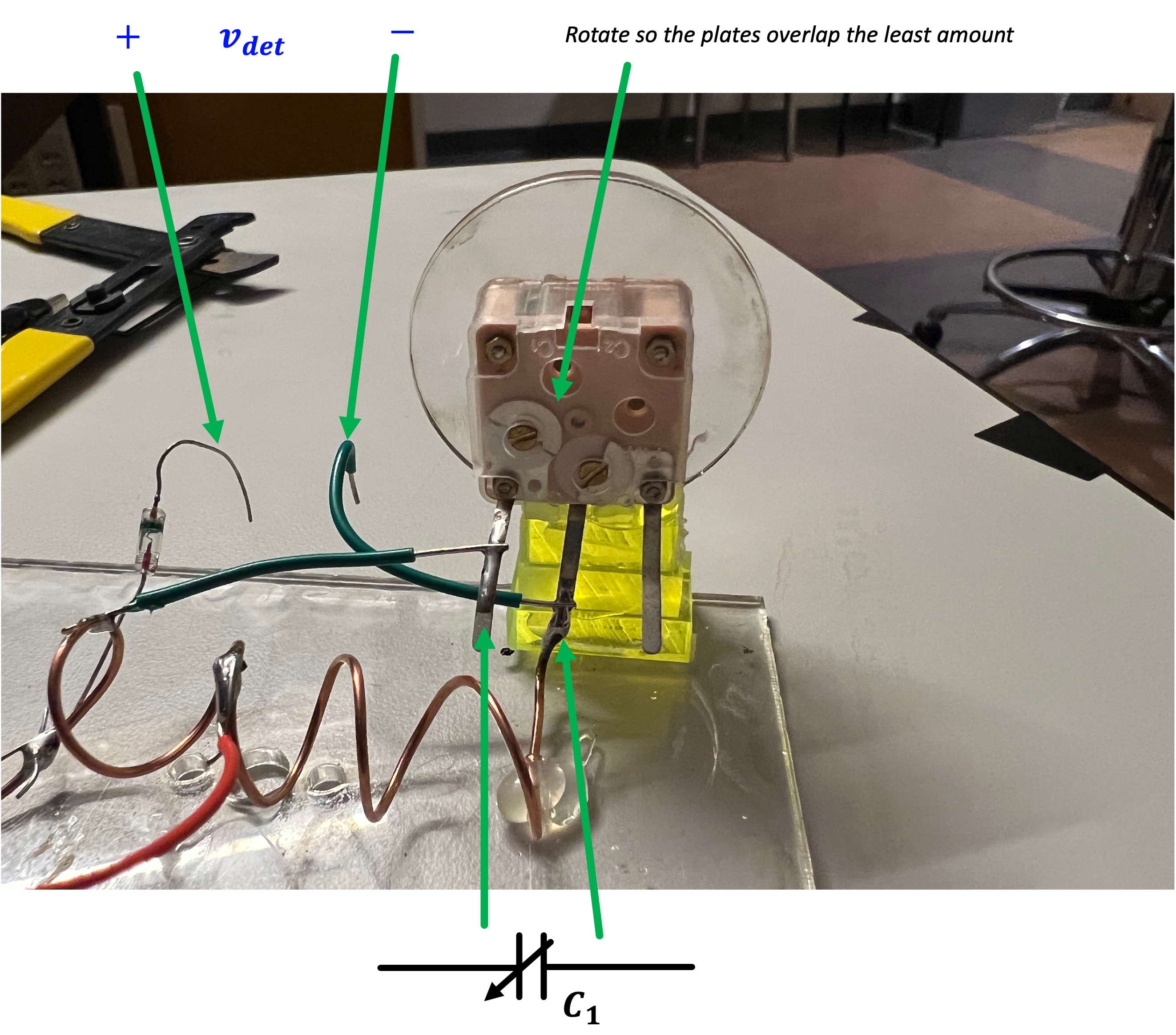
The Tuning Capacitor C_1 is one of the weird junk ones I got in bulk from Amazon here. Honestly these caps suck for what we need since the low range of the capacitance is actually a bit higher than we want, but they'll do. We will just likely need to lower L a bit more in order to get our L\cdot C product low enough so that our resonant frequency can get high enough to cover the entire FM band. The variable capacitor has two capacitors on that share the common middle lead. Looking from behind the tuning cap, use the left pair of leads for C_1. In addition, use a flathead to turn the inset trimmer cap about 180 degrees from its starting location. This will allow us to get the lowest possible value for C_1 at the rightward limit of turning (looking at it from the front). I've laser cut some "knobs" you can mount using an M2.5 screw and washer. I made a nice single-piece mount for the capacitor you can see in my workin example in class. See my receiver at the front of class for how I mounted it.
- The Diode D_1 must be a germanium diode. This is important since the "turn-on" voltage of a germanium junction is very low...approximately 0.2V to 0.3V. A silicon diode, for example has a turn-on of 0.7V. "Turn-On" is a misnomer...it really refers to where the diode has a nice non-linear "kink" in its I-V relationship. We want that kink to be as low as possible since it means we can encounter some legitimate non-linearity for as small as signals as possible. If the signals were coming in huge, you could totally use a silicon diode or even an LED (with their really large turn-on voltage), but that's not the situation we find ourselves in. The germanium diodes aren't plentiful. So don't mess them up. When soldering, try not to keep the iron on them too too long.
- While we often think of diodes as "really" following the Schockley equation of some flavor like: i_D(t) = I_S \left(e^{\frac{v_D(t)q}{nkT}}-1\right), which would suggest that the behavior is arguably equally non-linear on its whole curve, in reality that's not quite how it works. There are other factors that come into play with diode curves and they usually won't work that way.
- As an aside, check out this cool site where some folks test out a whole bunch of different diodes and show their I-V curves. (scroll down for more filtered plots of sub-groups since that first plot is a bit overwhelming). You can see that they look exponential-ish but there's definitely an argument to be made that there's regions of linearness, then regions of "kinks" and then regions of other linear behavior. Hunt around through these curves and find Germanium, and particularly 1N34A. You can see that diode in particular has a nice kink in its I-V curve for relatively low values of v_D, which means, that we can hit that juicy, juicy non-linear region (with all of its higher-order Taylor Series expansion terms that give us multiplication and therefore demodulation as discussed in with much weaker signals than would be necessary with a something like a silicon diode.
Try to keep leads short where possible. Solder C_1 leads to the appropriate spots on the inductor using some wires with a little bit of breathing room so you can stretch the inductor out more if needed. Be careful soldering the coil. It is made of thicker copper so it'll take longer to heat up and will hold heat longer than you might expect.
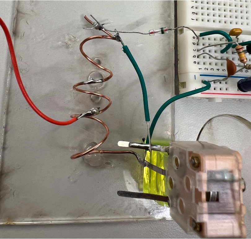
After the diode, you are in the land of low-pass (which for us is audio frequencies). Breadboards won't eat audio like they do RF, so the next two stages can be done on a breadboard (see how I set mine up). This is a bit more forgiving than all the soldering/floating wires. This includes the last two components of the schematic in Figure 1, which could be counted as either the output of our crystal detector or the input of our audio pre-amp (nex section) tbh.
- Resistor R_1 and Capacitor C_2 form a low pass filter which essentially filters out all the high frequency components of our nonlinear demodulation from D_1 leaving just the low frequency goodness that we care about (the actual information). There's some flexibility in these values. I just used ones sitting on my bench. You want to target their time constant \tau to be about 0.1 ms (currently 0.09 ms with these values). This will allow any audio signals through but block any higher frequency crap. While their product is important, achieving it with too high a resistor/too low a capacitor or vice-versa can result in weird loading so try to stay in this neighborhood of values for both of them.
Once this is built, you should have a crystal detector. You may be getting signals right now. If you hook the output up to an oscilloscope you might even be able to see something (tiny). Likely it will be underwhelming.
Let's move on.
The Preamplifier

Next up is a little bit of preamplification. We could go straight to a power amp but this lets us drive things a bit less hard so we get less distortion (we already have enough of that as it is with our slope detection scheme). This circuit is a classic common-emitter amplifier that is capacitively coupled on the input and output.
-
Capacitors C_3 and C_4 are AC coupling capacitors, allowing the audio through but blocking any DC bias which would mess up the individual stages and their operations. 1 uF is a good value to use here. I found a bunch lying around. You could got a bit higher probably lower and little change would result.
-
Transistor Q_1 is what does the actual amplifying. Any small-ish generic junk NPN bipolar transistor should work here. I used a 2N4401 since that was on my bench. I left a bag out of them. A 2N3904 or 2N2222, should also be fine, and likely work a bit better tbh. Remember arrow leg is the emitter, middle leg is base, top leg is collector. Looking at a NPN transistor from the front, leg order going left to right is Emitter Base Collector.
-
Resistor R_2 is giving us a bit of collector biasing which is a way of stabilizing the transistor via negative feedback so it is always in its active mode of operation. Using negative feedback almost always comes at the cost of a loss in gain, but usually we'd rather have a well-behaved mid-strength bull in a china shop than a roided up out-of-control bull in a china shop. Its high value ensures that not too much feedback is happening. The value can be played with. I used 9.1 MOhms since I had that sitting around. Going lower to a few Meg or up to 10 shouldn't matter. You do need some resistance though (don't leave it out), otherwise the transistors bias point will be all over the place.
-
Resistor R_3 somewhat determines our overall voltage gain and also interplays a bit with R_2 for the biasing.
Audio Amplifier

Alright last stage.
-
Resistor R_3 is our volume control. The signal comes in and drives a 10 K pot. We use the pot in its variable-voltage-divider format here drawing a fraction of the incoming signal out via the wiper arm. When turned all the way to the top, the pot will cause max volume in the amp...when turned all the way down, it'll turn the amp off. 10 K is a good value to use here. You could go lower, but not too low. Interestingly, you may find "max" volume does not come from having this pot at one extreme or the other but rather at some midpoint. This is related to impedance matching with the input bias resistors of the next part. Don't worry about that.
-
The audio amplifier chip U_1 is an LM386-N1 or something like that (N3, or N4). This part can't vary too much. It is not an op amp despite what its symbol looks like. Rather it is a self-contained class AB amplifier meant for driving low-ohm speakers. Pay attention to the pins. If you want to really make some noise add a 10 microFarad cap between pins 1 and 8 to add some "bass boost" lol. There are other parts we can wrap this chip with to improve noise and things, but I gotta be honest...you're going to have so much noise in your signal that it is not going to matter so its whatever. I have a mix of LM386's at the front in a box. All of them should be fine, even the counterfeit/reject ones with the suspicious National Semiconductor logo on them.
-
Capacitor C_5 is a standard beefier DC-block cap. It ensures no DC will go through the speaker and burn it out. It will be an electrolytic cap at this value so make sure to put the + end towards the amp. Nothing will blow up if you don't, but over time it can get weird. 10 uF is a good value, though go larger if you want. We likely won't have much bass to really pass anyways, so larger values (Which pass lower and lower frequencies) aren't going to be doing too much.
-
Speaker S_1 is a regular junk 8 Ohm speaker. I have some lying around. Use one.
Putting It All Together and Testing
OK so once this is all wired together, power it up. 12V is good if you're on the bench supplies (we'll also use 12V with our vacuum tubes eventually later on). I have some 9V and clips and batteries if you need them as well for moving around to find signals. This could also be good to take it home if you want.
For testing and tuning, you need to realize a few things:
-
First, make sure you audio amplification pipeline is working. It would suck if it isn't. Touch the input to it with your finger. You should get some nice buzzing out of the speaker. If not, check your volume pot and wiring. Make sure this is working first since we're going to rely on it (and our ears) to find stations.
-
When tuning, we are at FM so up in the 100 MHz range. The wavelengths here are a few (three-ish) meters which means that as you move around the room and rotate your antenna you will quickly encounter peaks and troughs of signal strength. This is cool, but can also be tricky. Lucky for us we are getting bathed in pretty strong FM signals on campus from some nearby commercial stations.
-
Have patience. You ever here that saying, "Don't get angry when you're stuck in traffic because you're part of the problem"...? Same thing here. You and your flesh with all its ionic juices are part of the tuning. When you are near your coil and capacitor, your body is adding/modifying those values. Embrace it. There's no shame to say, "well I get this station if I touch the coil with my finger and hold my arm this way." It takes some playing but hunt for stations.
-
These variable capacitors are kinda junky. They have some backlash in them so sometimes tuning into 17 pF from the left will work better than tuning into 17 pF from the right. As you learn more about your receiver you'll start to get a better sense of what works and what doesn't.
Is it Working?
If it is working, feel free to take a video to commemorate. You can hang onto the amplifier or put it on top of a bench with your name and a "DONT'T TOUCH" note if you want. Don't dissassemble the parts. We'll eventually use the front-end part for some improved receivers in future labs and the amplifier pathway can be good to play with our tube circuits.