Tube Op Amp
An Op Amp from Tubes!
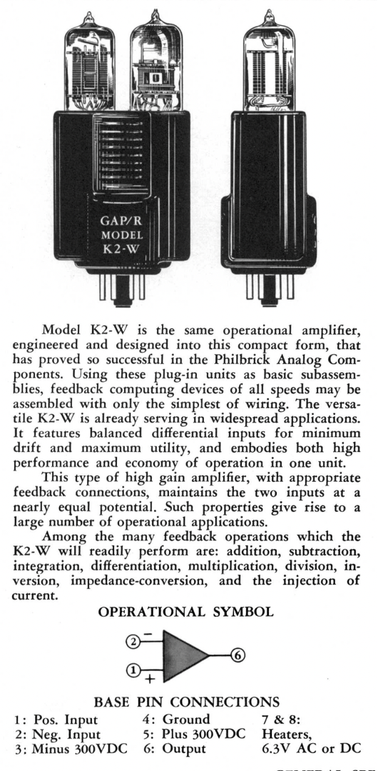
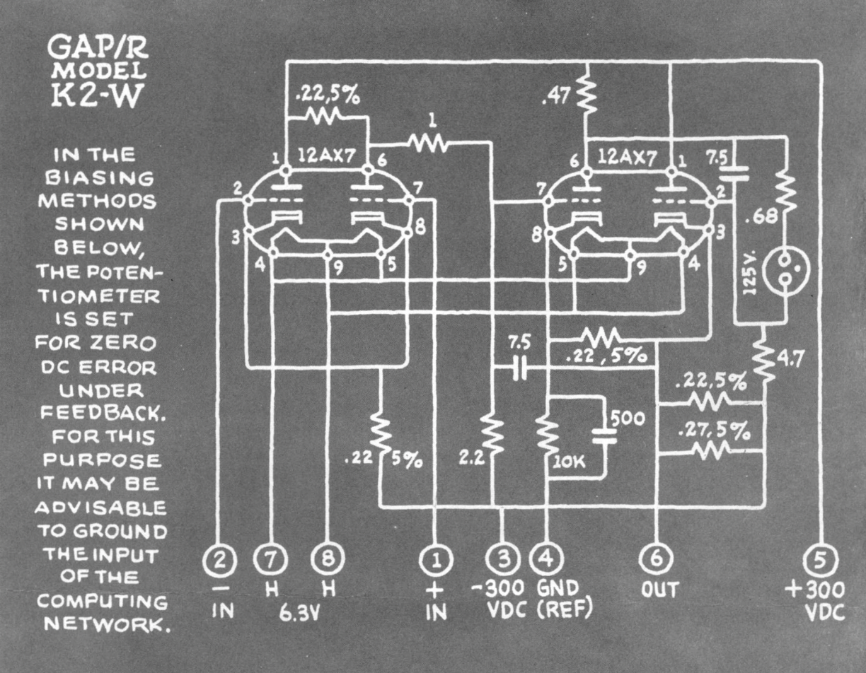
The schematic is actually pretty funky. The fact they could get a somewhat decent op amp out of just four triodes (two dual triodes) is really a testament to their talent as EE'sThe left triode acts as what is essentially a balanced differential amplifier. The first half of the second tube takes that input and basicaly acts like a common cathode gain stage. This is then fed through some neon lamps that are doing some level-shifting behavior, which tbh I'm not 100% clear on, but is kinda related to them acting like a fixed-voltage source, before going into the other half of the final tube which is a form of cathode follower (a buffer). The circuit benefits/needs a particular type of dual triode, the 12AX7 which is a very high gain tube...a high gain will actually help with a lot of things in the circuit (we'll see in some math later).
Ok so let's build a kinda-version of this. We'll use three tubes, in particular those 12V pentodes I have a bunch of. The first two will be used for the differential amplifier, and the third will be for the cathode follower. We won't have a extra stage of gain or a level shifter so our op amp will not be able to be used in a DC-coupled fashion (we'll use the output through a capacitor when using feedback).
So to get there let's walk through some basic circuits.
A Single-Ended Amplifier
Consider the standard amplifier topology we've been looking at the last couple weeks. Input at the control grid, output at the plate (aka anode). In a circuit like the one shown below, we can assume grid current is negligible so the current into the plate is the same as the current out of the cathode, i_{Q1}.

Now tubes are non-linear devices for sure, but we can roughly say that the current i_{Q1} is related to the grid-cathode voltage scaled by a transconductance term (which tells us how much current varies for a variation in voltage). You'll see this usually with the term g_m. For our circuit, let's call it g_{Q1}. The total expression of current i_{Q1} is therefore:
If the cathode is tied directly to ground this equation is very simple, but in the case of a tube with a cathode resistor R_K we have some negative feedback going on. v_k is itself based on the value of i_{Q1} through Ohm's Law, so that means really:
Readjusting this to isolate i_{Q1} we would then get:
The output voltage will then be based on:
Ignoring the DC 12.6V term for now our "signal" has an equation of:
Now looking at this equation the ability of v_{in1} to cause a change in the output is inhibited by the presence of R_k...as R_k \to 0 it will simplify back to the basic i_{Q1} = -R_1\cdot g_{Q1}\cdot v_{in1}. If R_k is not 0, however, then it makes the denominator larger than 1, cutting down on gain. How much it messes with the denominator is based on the battle between it and the tube transconductance term g_{Q1}.
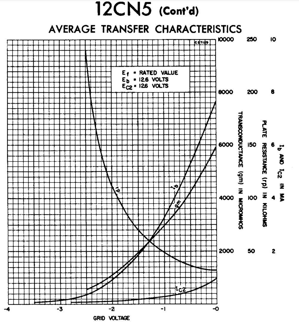
As we can see from the plot, the transconductance is likely somewhere in the neighborhood of a few thousand "micromhos". I'm not going to obsess over what it is exactly, but knowing that it has a value of like 0.001\mho that means R_k likely needs to be at least into the ~100's of \Omega before it starts to have an decent impact on the overall denominator term.
Let's build on this circuit in the next part.
A Differential Amplifier
Now consider the topology below using two pentodes. They each have an input and each have an output and are generally separate with the exception that they share the cathode resistor R_k. Because each side depends on the voltage at the cathode to determine their current, and that cathode voltage is based on the sum of the two currents from the two pentodes, this provides an opportunity for the input/behavior of one side to impact the behavior of the other side.

Just like in the single-tube situation, you can derive an isolated expression for i_{Q1} and i_{Q2} in terms of only system inputs (v_{in1} and v_{in2}). The algebra is a little messier and there are a few more substitutions, but it isn't too bad. We can make our life simpler by assuming the circuit is symmetric, with R_1=R_2=R and g_{Q1}=g_{Q2}=g_m. Doing so you can end up with an expression that looks like:
and
If we treat "v_{out}=v_{out1}-v_{out2} as the "output" of this circuit we'll end up, interestingly enough, with an equation:
or if we just call our input the differential voltage v_{in} = v_{in1}-v_{in2}$ we have:
This type of circuit is called a differential amplifier and is really useful in a lot of sensors and other things. It can remove common voltage between two signals, only amplifying the difference in the process. This is really nice since often times, the common voltage might be a bias voltage or noise...basically thigns we don't care about, and the signal is the difference between these two voltages.
An Operational Amplifier
OK now let's do a slight deviation on the previous circuit so we can make an operational amplifier. One of the nice aspects of an operational amplifier is it is a differential-to-single-ended circuit with low output impedance and high input impedance.
As stated, the current through each half of a diff amp can be found in a roughly closed-form solution. For i_{Q2}, if is, for example:
If we then use that value in conjunction with its plate resistance, R_2, we can determine that its output voltage v_{out2} is:
When v_{out1} and v_{out2} are used together in differential format, the single-ended terms end up kinda canceling out so you get a pure differntial signal. Just using one output though has two clear terms:
- v_{in2} which is based solely on v_{in2}...this ia single-ended input
- g_m R_k\cdot\left(v_{in2}-v_{in1}\right) which is based on the differential input.
This is not really ideal since we'd like one or the other...and for our case, the latter specifically in order to make an op amp. However, studying the relative weighting of those two terms we can see there might be a possibility for the differential term to dominate if g_m R_k can be decently larger than 1. Knowing that g_m is in the few milli-mho range, means if we start getting a R_K at a few KiloOhms we might land in a situation where the differential signal could have ~10 times the influence on the signal as the single-ended signal.
So that's just we'll do.
The circuit below starts with the differential amplifier from before and puts in some variable resistors for the R_1, R_2, and R_3/R_K. Resistors R_4 and R_5 are used for some minimal grid-leak biasing on the control grids of the tubes. You as the user should tune those once built. The output of the right half of the diff amp is taken for this stage's output. We take that output and feed it into a cathode-follower stage that provides some buffering/lowers the output impedance. As a result, with just three tubes we have what is kinda a operational amplifier.
The v_+ and the v_- are the non-inverting and inverting inputs, respectively, and the output is v_out. This op amp will have several issues with it:
- The open-loop gain will be really low, like 10...that's about what I could get. What we really need is another stage or two (and maybe even some positive feedback like the K2-W uses), but I wanted to keep the tube count low and we also will have a hard time doing it with such a narrow B+ supply. It is enough to get the point across for the lab.
- The output will have a big offset. It will not be centered around 0V. This is because we lack a way to easily level-shift and get back to around 0V. This will preclude us from hooking the op amp up in true DC negative feedback (since this offset value will screw everything up).
- Somewhat related to the last point, this op amp runs off of only 12.6V and 0V power connections. It is not a +/- supply type design like the original K2-W or like how many integrated circuits op amps were even. Its output will be centered at some weird kinda-mid-rail voltage based on the bias point of the diff-amp. It is what it is.
So build this circuit. The next section will talk about how to tune it.

Testing
Believe it or not, the circuit gives us an operational amplifier. I would never run to Ray Stata and tell him this is a good op amp, since it has some caveats for sure, but it can do everything an op amp should do. It has earned the right to be abstracted away into a new symbol so we'll do that. This is our op amp:

To test/tune the op amp, what we'll want to do is hook it up to a function generator and observe the output. For an input signal, I suggest a 10 kHz sine wave of about 300mVpp. Make sure to tell your function generator to have a hi-Z output since your tube's input will be high-Z. While observing the output of the op amp, adjust resistors R_1, R_2, and R_3 to get the maximum output signal. Remember, the signal will probably be on-top of a DC-offset value...so if you put in a 300 mVpp signal, you might get a 3Vpp output signal but it will be centered around 7V or something. That's fine.

Once you've gotten your system's gain maximized, the next step is to start running it at a higher frequency. Crank the frequency of your signal up until you start to see the amplitude drop significantly. Make note of what frequency you see that at.
Let's fix it with some negative feedback! Now...we can't hook the op amp up with direct DC-coupled negative feedback because of the offset the output. Instead what you should do is add feedback via a capacitor to block the DC (yeah it adds some phase offset, but we can ignore that). 1uF should be fine. You'll have something like the following:

Now run your frequency analysis again. First you should see that the gain is all gone...we've made an op amp buffer with this thing so that shouldn't be a surprise. But what you should see is that this circuit can go further up in frequency before starting to roll off and lose amplitude than before. What we've done...is trade gain for frequency range. This is a big deal...this is Black's Theorem...this is one of the foundational concepts of all modern engineering.
Now can we go somewhere between open loop and fully closed loop? Of course we can. In the first circuit we fed back 0 information to the input. In the second circuit we fed back everything. Let's feed back a portion of the output...given a signal, how can you make a fraction of it?...why a voltage divider will work. Let's add two resistors to divide the amount of voltage we feed back like so:

And that is your standard op-amp feedback circuit....as drawn this is a non-inverting amplifier, though we could swap the ground connection to R_B and the non-inverting input to get an inverting amplifier as well...and basically any other op amp circuit will work with this. Pretty cool. You should see a general trend of more gain, means earlier frequency roll-off...less gain...means higher frequency rolloff. You should also see better linearity...so instead of having a poor, nonlinear gain of "8", you could have a much better, closer to linear gain of "3". Another benefit of negative feedback.