Tube Oscillators and Pentodes
With An Advanced Tube
Tubes Driving Tubes Driving Tubes...
The circuit you'll build on this page is essentially a snake eating its own tail. One stage drives the next stage which then drives the first stage...and so on. Unlike with the snakes though, there's no self-destructive symbolism in play. Circuits of this type achieve very useful functionality and really touch on a whole lot of concepts, feedback, digital electronics, stability, time-constants, love, pain, beauty, etc...the list goes on.
The circuit at the core of today is known as the multivibrator. They were first developeda around 1919 and were made possible because of the amplifying and inverting nature of your basic triode/tube circuit like shown below. You'll recall from our class that in this standard configuration for a triode, you can get amplification, but the amplification will have a negative sign...so input voltage goes up a little, output voltage goes down a lot, input voltage goes down a little, output voltage goes up a lot. You get gain in terms of signal, it is just flipped.

Digital circuits were still a ways off, but the triode circuit above, could be thought of as a primitive form of inverter. If we just classify our voltages as either "high" or "low" you can abstract a circuit like that with the following symbol:

Inverters on their own are kinda boring. It is the "jerk" of circuits, always doing the opposite of what you tell it. However, that simple action, when linked together in feedback loops with other devices doing the same thing, can lead to very interesting behaviors as shown in the figure below. Certain configurations can result in stable circuits and other configurations can result in unstable circuits.

Early inverter-chain circuits were largely concerned with the two inverters. When driving eachother directly, you'd end up with a stable circuit that could hold a value. This has use as a state-storage mechanism and it was originally developed as Eccles-Jordan circuit. Alternatively, when you added high-pass filters in your chain, like shown below, you could get unstable circuits, but, importantly, these circuits could be predictably unstable resulting some nice oscillations based on the values of the C and the R which you choose:


We're skipping a lot of math here in there interest of brevity, but the unstable or "astable" inverter chain, is the circuit we'll build in this lab. This was developed/discovered around 1919.
Let's build this circuit except we'll do it with pentodes. The triodes we used last week could certainly work, but we should get more reps with pentodes. They'll also work a bit better at low voltage because I have some pentodes that "kink" over with very low voltages. Also the pentodes I have are actually meant to run at low voltage (and the filament is the same as the plate voltage so it is almost like we're working with modern electronics).
The Circuit
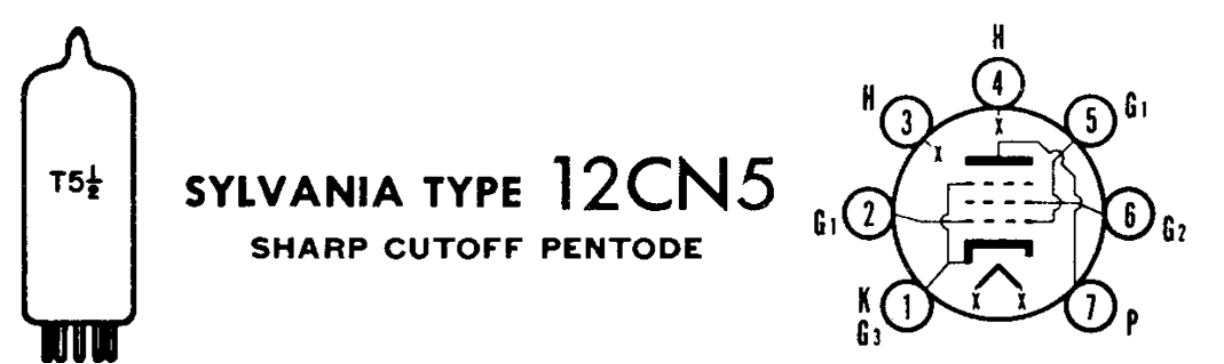
We'll be using two low-voltage pentodes, the 12CN5. They are interesting tubes on their own, but we're using them also because I was able to get a bunch of them for next to nothing... I think a guy was going through a divorce or something, since I got 400 of them on ebay for about ten cents a piece all-in, including shipping. Anyways, the 12CN5 is an interesting tube since it was developed in the latter half of tube-dom in the 1950s. It was meant for use in car radios and to operate only using the 12V battery directly. As a result, the filament and the plate(!!!) can actually run off of the ridiculous low value of 12V (12.6V to be precise).
The tube is a pretty standard pentode. The control and shield grids are free to use however whereas the suppressor grid is tied to the cathode as you'll often see. It is a seven-pin tube like last week (only one per package). The datasheet for the 12CN5 is here.
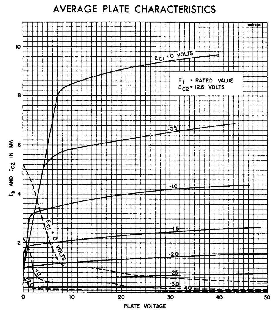
The I-V relationships of the tube, right out the datasheet is below. You can see it actually is over a range of voltages that are reasonable to our modern eyes. The max plate voltage is 16V as per the datasheet, but for whatever reason they give us I-V curves out to several times larger than that....not sure why.
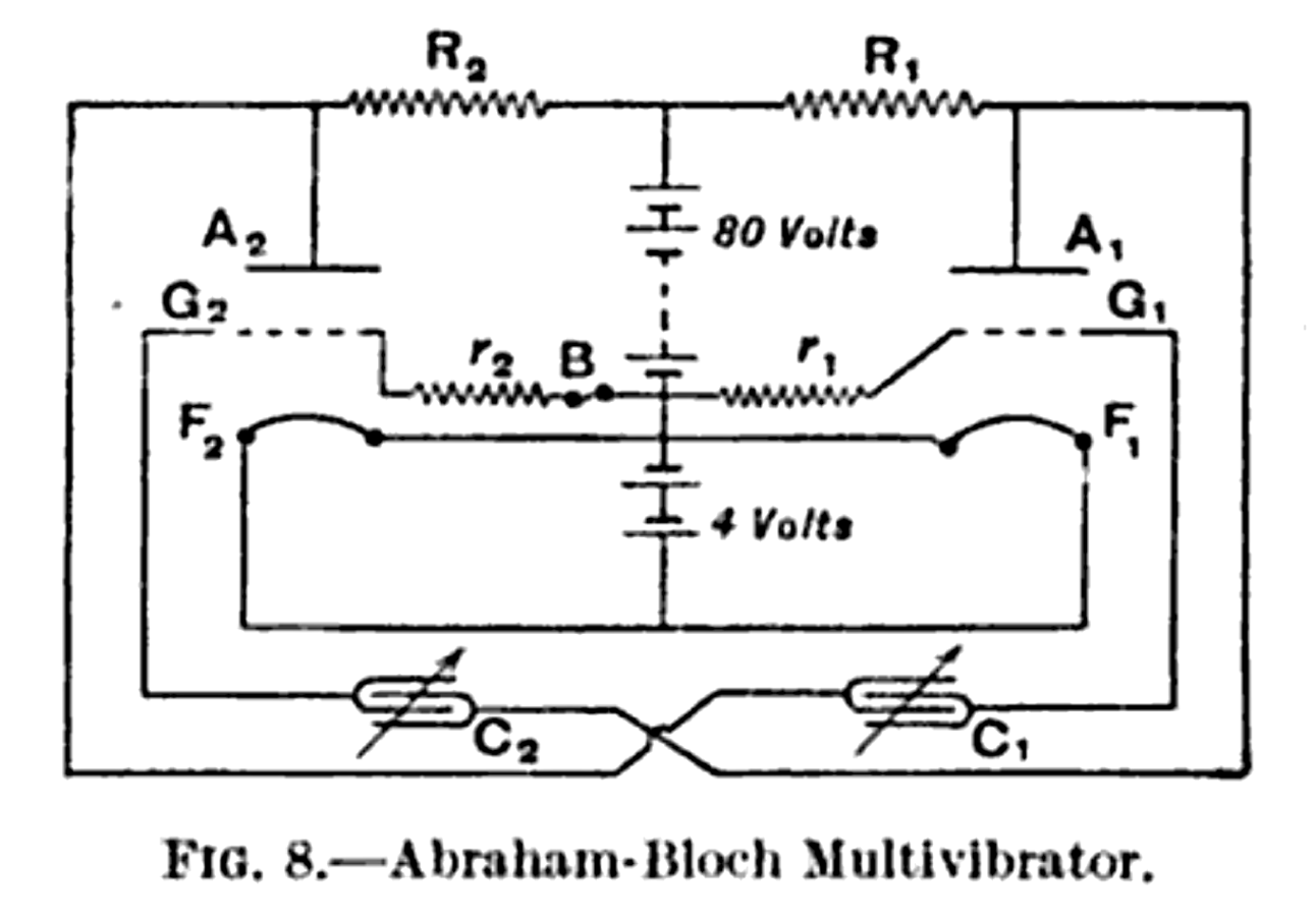
Anyways we're going to build the following circuit, a Abraham Bloch multivibrator. The circuit is essentially two inverting amplifiers driving one another and linked through high-pass filters, which means collectively they are unstable as a whole under many conditions. With the right tuning, the circuit will oscillate.
The purpose of the parts (keeping in mind each half of the circuit is a duplicate of the other):
- Pentodes Q_1 and Q_2 are the 12CN5 pentode active elements. They open the door up for circuit gain.
- R_1 and C_1 and R_6 and C_4 provide some cathode biasing for their respective tubes. The capacitors are doing that thing where they short out the resistor at "AC" frequencies, while still allowing the resistors to bias the tube at DC.
- R_2 and R_5 are the load-line/gain setting resistors for each half. Gain of each half is roughly related to these values (so large value means more gain). Feel free to experiment.
- C_2 and R_4 and then C_3 and R_3 are a combination variable output high-pass filter and grid-leak bias for each tube. Notice how the output of Q_1 connects to the input of Q_2 and vice-versa. That's that feedback process going on.
- The Piezo element S_1 is a high-impedance output that will respond to audio-frequencies. We'll use this here instead of a regular speaker to avoid loading down the circuit. If we used a speaker, even with a impedance matching audio transformer, the circuit would be asymmetric enough that we'd mess up the oscillation...so we'd need to add in a cathode follower (at a minimum) and likely a fourth tube to drive the actual speaker...so we'll just use this for now.
Build the circuit. Notice the A and B+ supplies are identical!...12.6V Much harder to mess up.

Build and Analyze
Build the circuit and test it out. An oscilloscope and the voltages at the two outputs will be useful to monitor. Start by positioning R_4 and R_3 in the middle of their range, adn vary them until you find an oscillation region. Feel free to then vary the feedback capacitors (or bypass capactors or whatever), to see what types of frequencies you can get.