Lab 4
Solid State Triodes: A Potential Replacement for the Vacuum Tube?
In this lab we'll be building a five-transistor (option for a sixth if you'd like/need it) germanium PNP audio amplifier. The circuit will run on 6.3V and consume probably 2% of the power of our previous tube-based designs while delivering superior audio. The technological progress will be palpable. Here is the audio amplifier playing some of Belle and Sebastian's 1996 If You're Feeling Sinister.
The Setup
Towards the very end of 1947, engineers at Bell Labs developed the first functional transistor, and in the years following, the device was perfected and developed rapidly. While the majority of modern (2024) transistorized electronics function using the Field Effect (forming Field Effect Transistors aka FETs), early transistors were point contact before evolving into bipolar junction transistors (BJTs) which were the dominant version up until the 1970s. Furthermore, in the first decade of transistor development, germanium (not silicon) was the semiconductor of choice. Germanium, which we've already utilized as a detector in the earlier FM radio, is in the same column as silicon in the periodic table.
While both NPN and PNP type transistors were developed early, due to various fabrication challenges and difficulties, PNP-type were the transistor most widely available at least at first. This was particularlarly interesting to a field of engineers coming from vacuum tubes. In particular:
- The devices used very low voltages (often below 10V) where previously, tubes would need 100's of V to run properly.
- The devices used very little power (mW) where previously, tubes would need Watts just to even work. This is because the generation of charge carriers was "built-in" to the transistor's material properties whereas tubes relied on thermionic emission (which could only be obtained via inefficient resistive heating).
- BJTs were current-controlled current-source devices, as opposed to tubes which are voltage-controlled current-source devices. This required different ways of designing and thinking about the circuits.
- PNP BJTs (the most-common type at first) relied on holes as the charge carriers rather than electrons. This mean that the electrical positioning of BJTs was backwards to tubes. The "source" of the charge carriers (emitter in BJTs and cathode in tubes) was at opposite voltages.
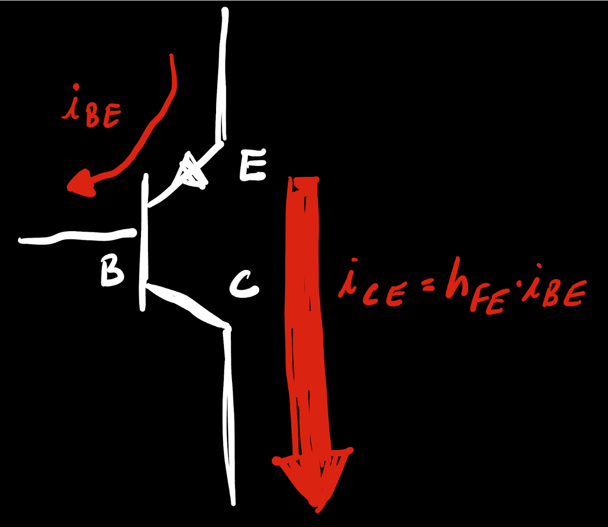
A PNP BJT worked by injecting a certain amount of current into the base-to-emitter. This current would then result in a much larger current flowing from the collector to the emitter. There would be an amplification factor h_{FE}, which was actually a calculated slope from the device's I-V characteristics that would relate state that i_{CE} = h_{FE}\cdot i_{BE}. This amplification factor could be in the double-digits or maybe even a hundred or so.
One down-side with BJTs compared to tubes was that since they used an input current at their base to amplify, they usually had much lower input impedance than tubes.
In the United States, Western Europe and Japan, commercially available transistors started showing up in the mid-1950's. Many of these models like the CK722 are quite hard to acquire today, and when you can get them, they'll be very expensive to the point that building with them isn't a good idea. They just were not produced for that long just because newer and better models came around very quickly. Couple that with the fact that transistors didn't fail at the rates of tubes and the early ones didn't stick around long-enough to get included in a lot of early commercial (i.e. large volume) equipment, and there just aren't the massive warehouses of 50's germanium transistors like you see with tubes.
However at the same time, on the other side of the so-called "Iron Curtain" existed a land where production quotas were almost completely decoupled from actual demand. As a result, many styles of early transistor (or equivalents) were manufactured in huge numbers up until the early 1990's. We can acquire and use these quite easily to build our circuits.
Soviet Transistors
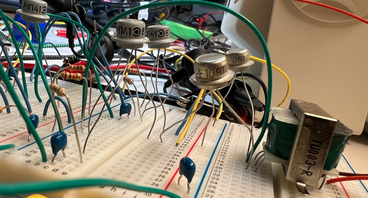
The circuit we'll be building will use two different Soviet-era germanium transistors:
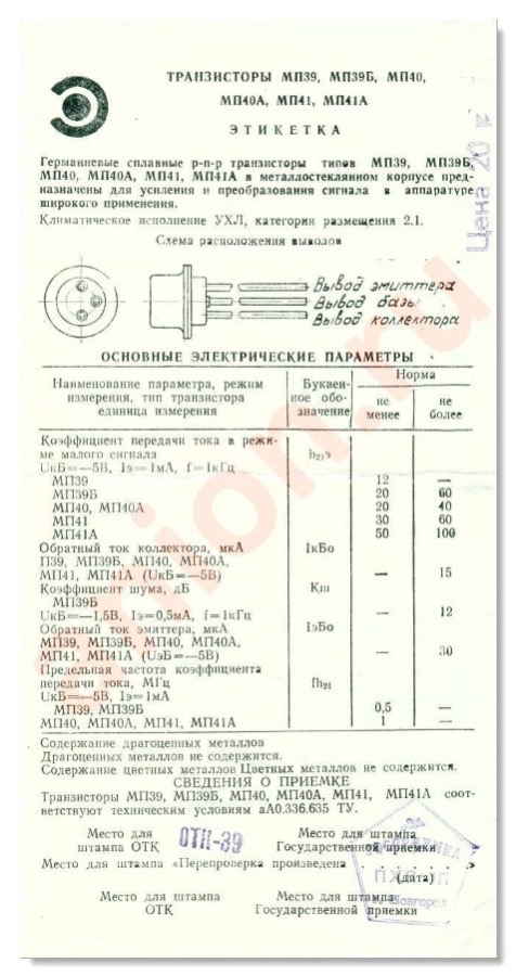
- The MΠ41 (or MP41) PNP germanium transistor: This is a low-power decent generic transistor. We'll use it as a pre-amp of sorts. It is capable of a current gain of <100 and output currents of maybe 10 mA.
- The MΠ20 (or MP20) PNP germanium transistor: This is a mid-power decent transistor. We'll use this as a power-amp. It is capable of current gains closer to 50, but an output current of 100 mA or more depending on biasing.
Both transistors come in a cool flying-saucer like packaging. The MΠ41 that we have are a nice painted grey color. The MΠ20 transistors are in their raw aluminum can.
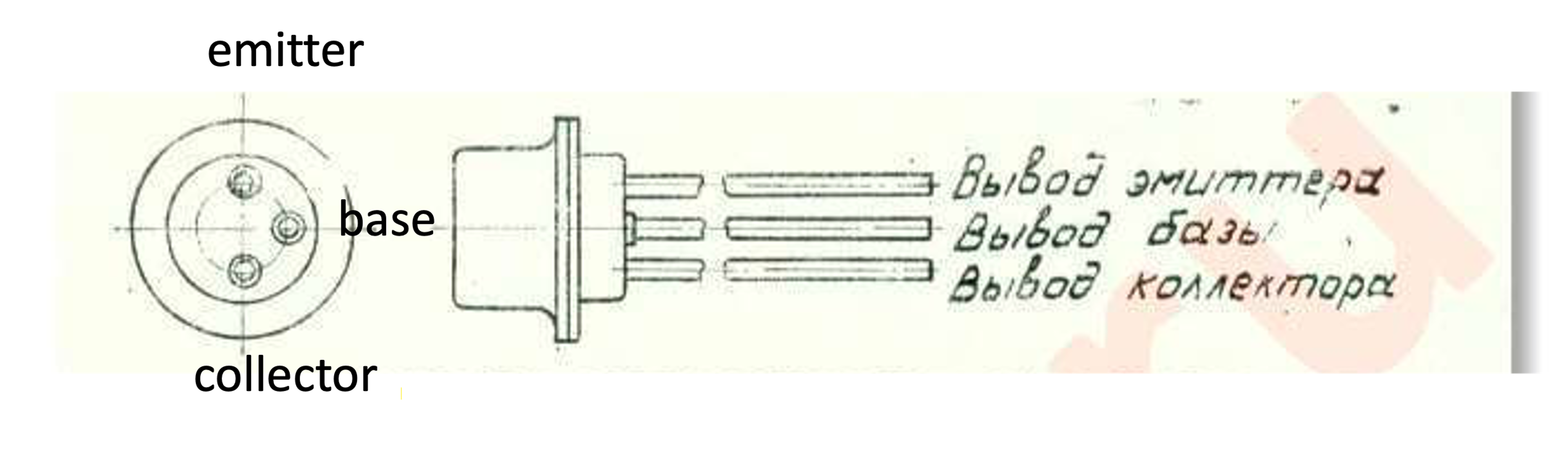
Both transistors have the same pinout:
The datasheets for these things are actually hard to get. The MP41 datasheet with just rough specs I grabbed from one of the boxes they came in:
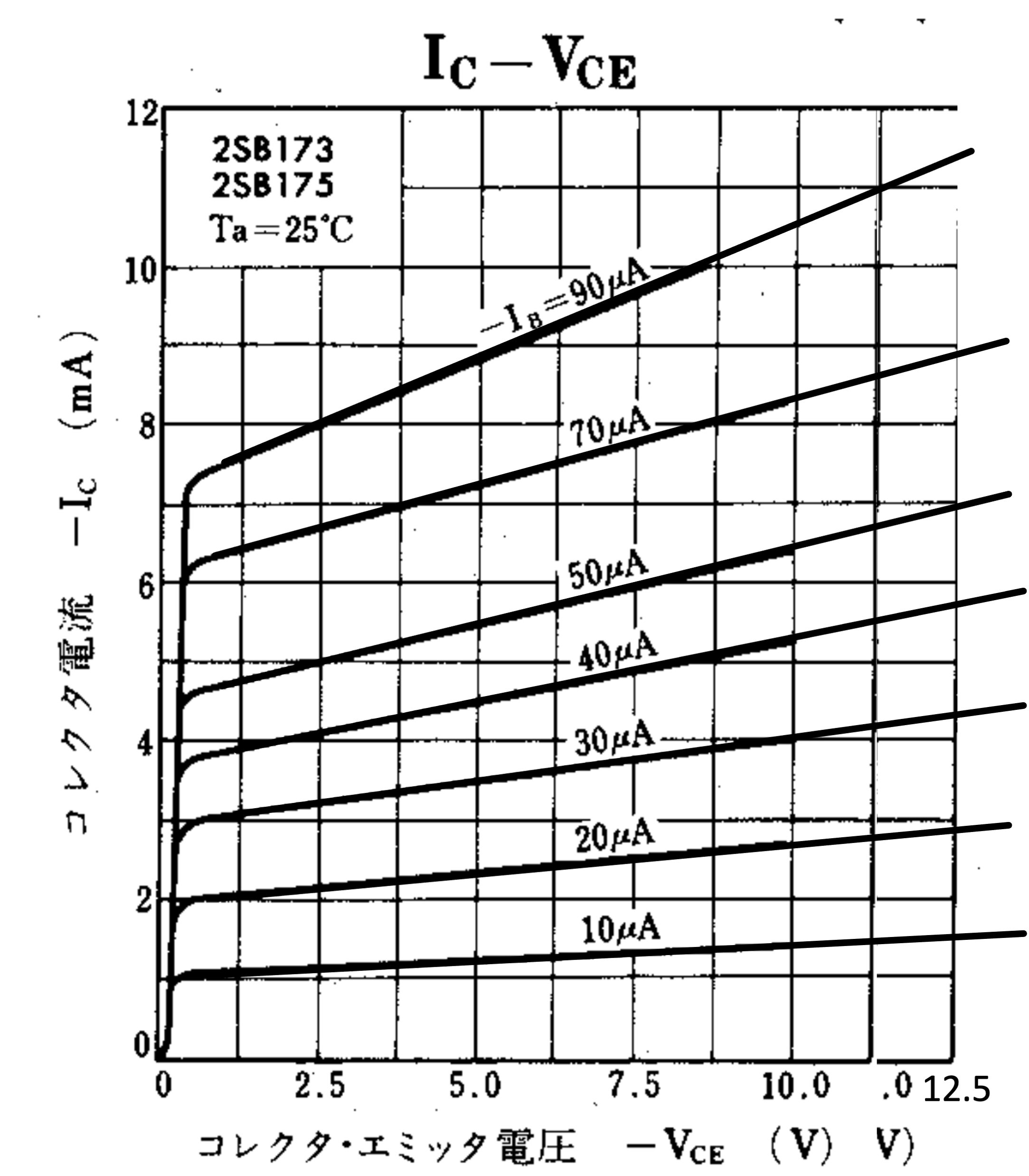
The I-V curves I could find for the transistor however come from an "equivalent" model manufactured by a Chinese company in the 1990s.
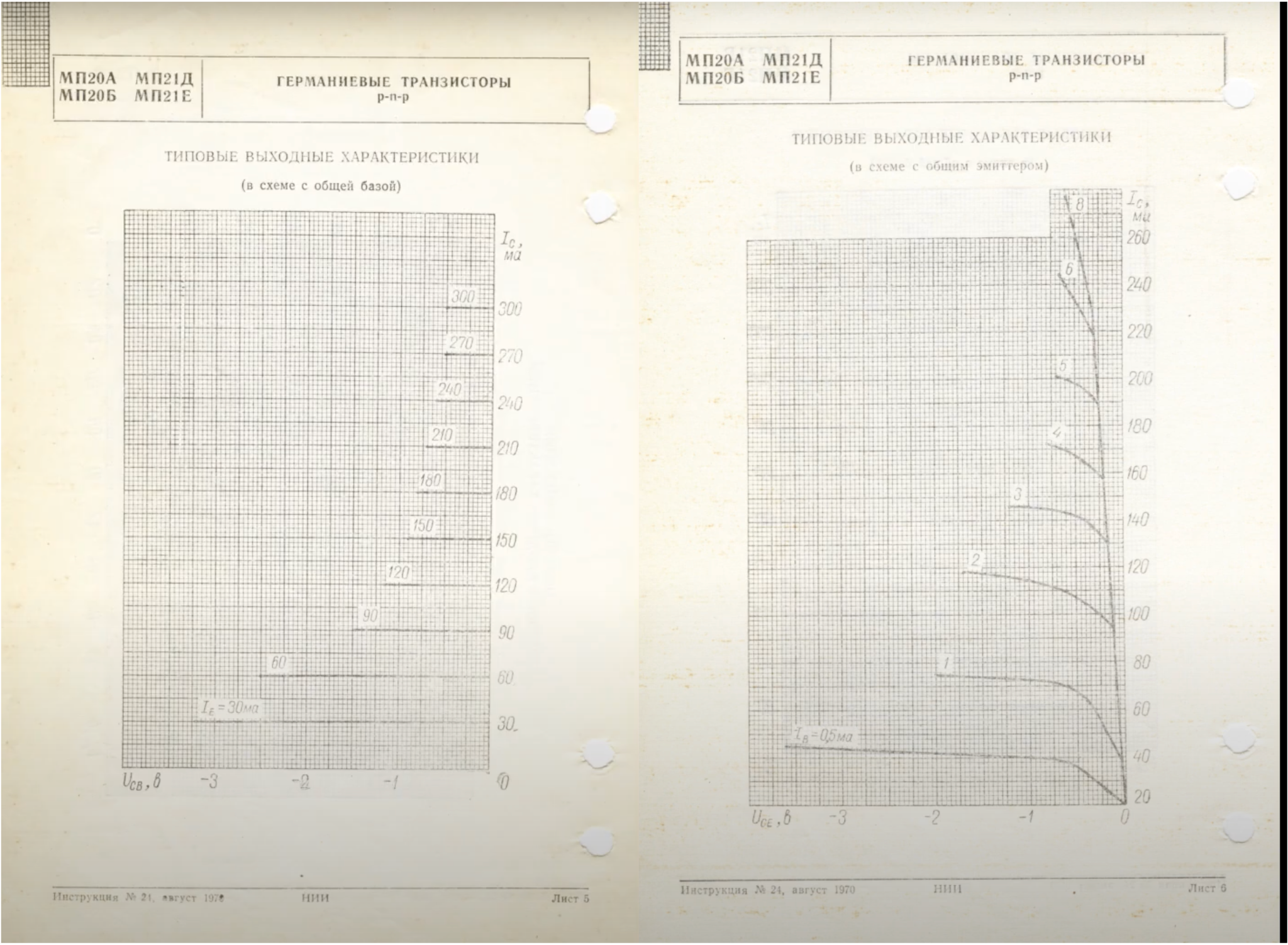
The MP20 datasheet is actually harder to get. I found it on Youtube, of all places. Some channel is doing God's work putting these hard-to-find datasheets in a accessible location, but using the absolute worst means of disseminating the information (videos of pdfs...who does that?). Anyways, go to Open Electronic's youtube channel and smash that mf-ing like button.
Here's a screenshot from the relevant pages showing the I-V curves for the MP20. Notice they actually have two sets of curves...one from the BJT in saturation and cutoff modes and one in active mode. Interesting. Don't see that too much.
Phase Splitter
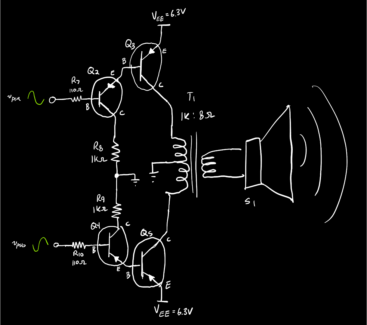
OK what are we building? This circuit will be kinda similar to the tube amplifier you built. It'll be a push-pull amplifier but since we're driving only P-type transistors, we'll need to use an audio output transformer with center tap to merge their signals. A push-pull amplifier will need a phase splitter, however, and we can do that with only one transistor using the following circuit:
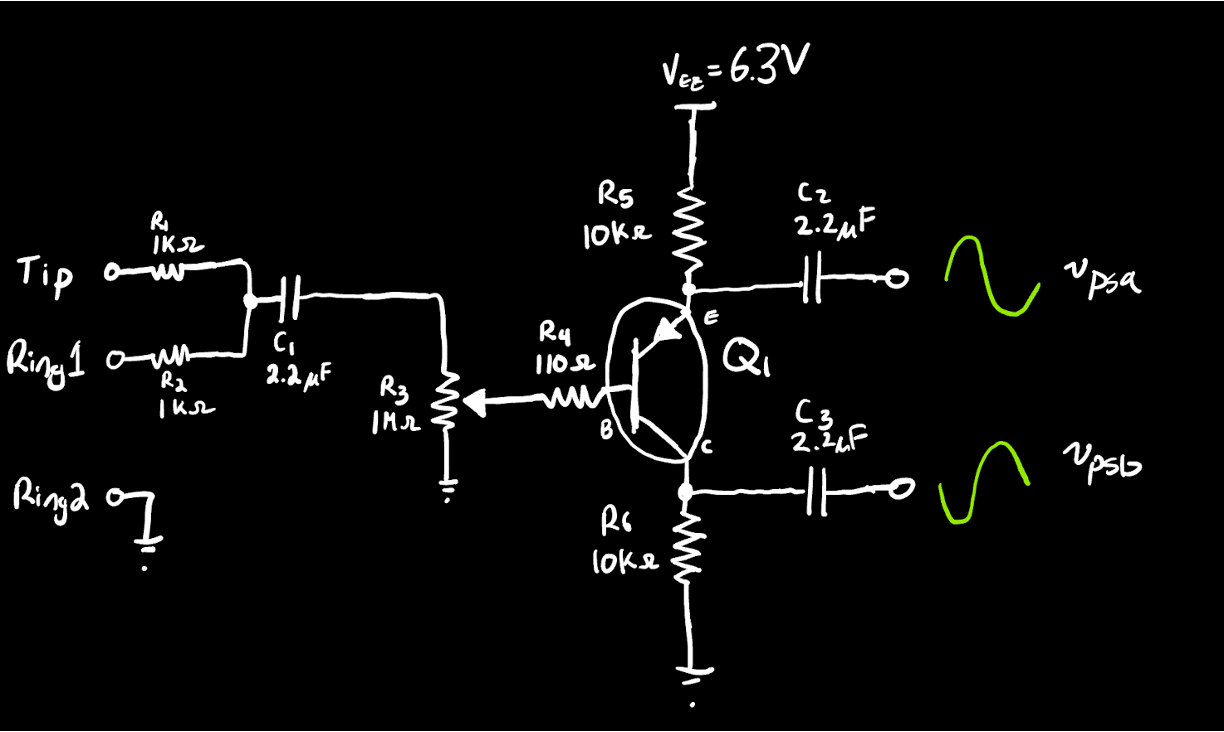
The phase splitting action of this circuit comes from the fact that we're tapping the the resulting amplified current both above and below the transistor. In the top resistor R_5, as current increases, the voltage being measured will go down in value from its operating point (since the other leg is pinned at 6.3V). In the bottom resistor R_6, as the current increases, the voltage being measured will go up in value from its operating point (since the other leg is pinned to ground). If we capacitively couple these two signals out, you'll have 0-V offset signals of approximately the same amplitude but 180-degrees out-of-phase with one another. We could have done this with our tube amplifier, but because the voltage we were running at was so low, it would have been very, very hard to balance the two sides and we likely would have needed to add two additional tubes on each signal path afterwards anyways to try to get a better source impedance for the final driving stage. Anyways, with a transistor, this strategy will work perfectly fine. The output impedance of both paths here is a little higher than we'd like, but not awful. We'll address that in the next stage.
Power Amp
For power amplification and actually driving the speaker we'll use the MΠ20 transistors since they're capable of providing a lot more current (actually more than they are capable of handling and if you run this circuit wrong they can easily overheat themselves). But the output impedance of our phase splitter is a little bit too high for us to have sufficient current to go directly into the MΠ20 transistors. For the MΠ20 transistors to put out 10's of mA they need to be getting in ~1mA or more...but the full bias current of our phase splitter is itself only a few mA and we'd want to only tap a small amount of that for subsedquent stages...so there's just not much to draw out of there for driving directly.
Instead what we'll do is use two MΠ41 transistors, one for each MΠ20 to act as a mini-preamp for each MΠ20. Hooking them up roughly like shown is what's known as a Darlington pair. It takes two transistors and allows you to basically multiply their two gains (h_{FE}'s) together at the expense of some other features which we don't really care about here. The net result is a sub-circuit that act on its own like a really-high gain transistor (having a current gain of several thousand) which ultimately allows us to get output currents closer to what we want.
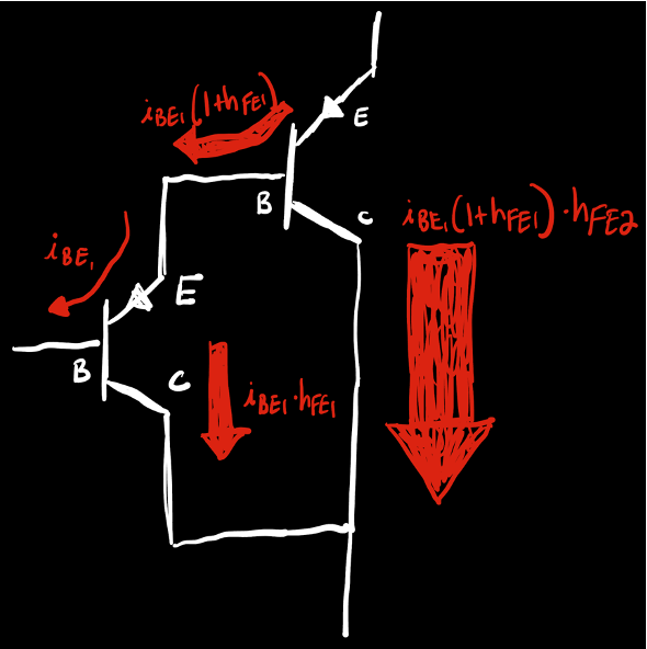
Interesting side-note, Darlington pairs were actually manufactured pretty early as units you could buy. Since they were comprised of two transistors on one piece of semiconductor this caused issues in the early sixties when the idea (and patents) related to Integrated Circuits started to show up.
Ok the circuit you'll build is below. It isn't a true Darlington configuration, but close enough. Note this is very similar in a lot of ways to the output stage in our tube amplifier from lab 02. Except we're in PNP transistors.
Finish the circuit and play some music.
Going Further
The circuit shown works well with a modern laptop providing audio. If you're working with even lower-amplitude signals you maybe need some more gain up front. In that case I'd put another MΠ41 in front of he phase splitter. If you have want to do this and/or have questions, let me know and I can draw out what's needed.